
Portable workstation for a ladder

a workstation and ladder technology, applied in the field of ladder attachments, can solve the problems of existing workstations and lack of horizontal work places

Inactive Publication Date: 2010-06-24
TYDINGS III WILLIAM F
View PDF46 Cites 10 Cited by
  • Summary
  • Abstract
  • Description
  • Claims
  • Application Information

AI Technical Summary

Problems solved by technology

Existing workstations are either permanently attached to the ladder, or do not provide a horizontal work place on the back of the ladder.

Method used


Image

  • Portable workstation for a ladder
  • Portable workstation for a ladder
  • Portable workstation for a ladder

Examples


Embodiment Construction

[0016]The following detailed description is of the best currently contemplated modes of carrying out exemplary embodiments of the invention. The description is not to be taken in a limiting sense, but is made merely for the purpose of illustrating the general principles of the invention, since the scope of the invention is best defined by the appended claims.

[0017]Various inventive features are described below that can each be used independently of one another or in combination with other features.

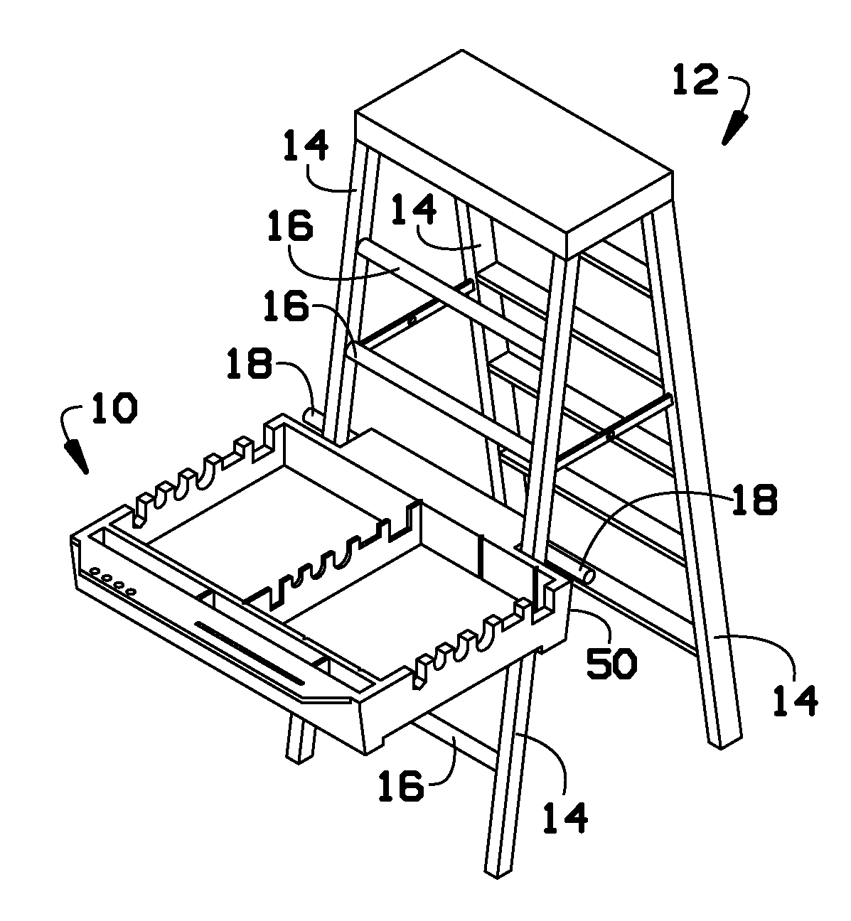
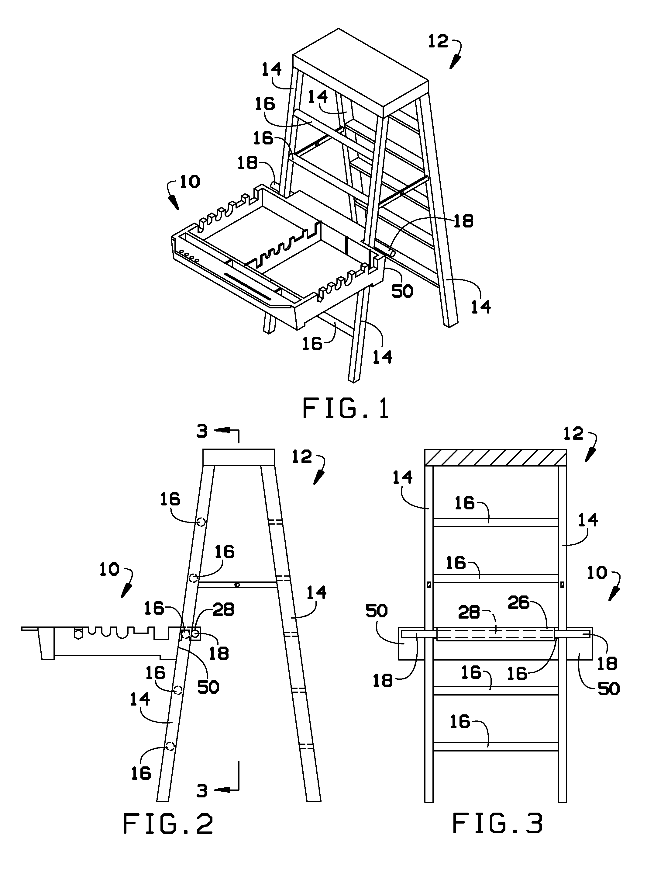
[0018]Broadly, an embodiment of the present invention generally relates to a portable workstation for a ladder.

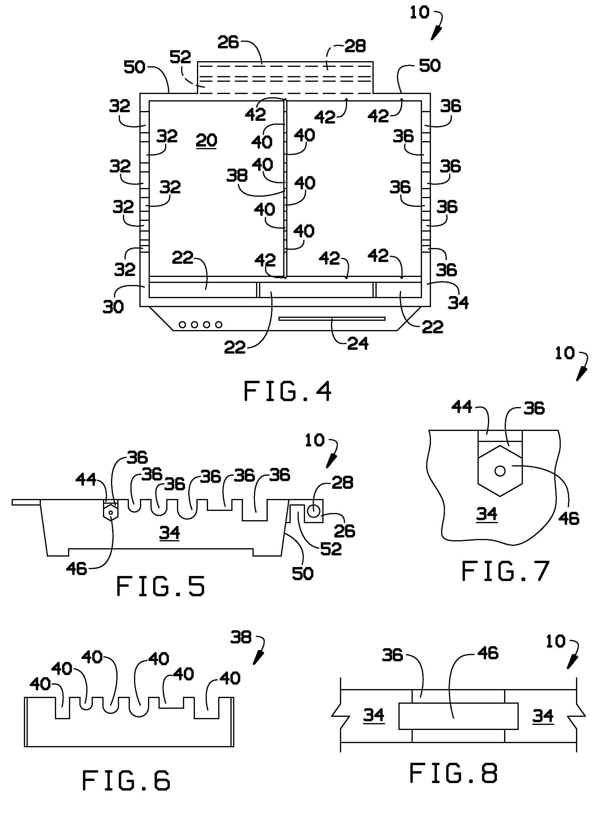
[0019]An embodiment of the present invention includes a rectangular tray device that will hold in place copper pipe, electrical conduit, ½″, ¾″ and 1″ sizes, all thread rods ¼″, ⅜″ and ½″ sizes, also ¾″ and 1.5″ support channel. As an example material, the tray can be made from, plastic, metal, or wood, etc. The tray depth allows storage space for tools and hardware, or the like.

[...


PUM


Abstract

A portable workstation for a ladder includes: a base section having a work area; a supporting surface adapted to rest upon an outer surface of the legs; a retaining section adapted to extend between and past the legs; a lateral cavity in a lower surface of the retaining section, adapted to engage with the rung; and a lateral aperture in the retaining section, adapted to receive a rod underneath the legs of the ladder that extends beyond the legs of the ladder so as to press up against an inner surface of the legs. When the rod is inserted into the aperture, the workstation rests upon the legs and rung, and the rod presses up against the legs to retain the workstation.

Description

RELATED APPLICATIONS[0001]The present application claims benefit of priority from U.S. Provisional Application No. 61 / 140,755, filed Dec. 24, 2008, which is incorporated herein by reference in its entirety.BACKGROUND OF THE INVENTION[0002]The present invention generally relates to attachments for ladders, and more specifically, to a portable workstation for a ladder.[0003]Existing workstations are either permanently attached to the ladder, or do not provide a horizontal work place on the back of the ladder.[0004]As can be seen, there is a need for a more efficient and effective portable ladder workstation.SUMMARY OF THE INVENTION[0005]In one aspect of the present invention, a workstation utilizing a ladder having legs and a rung between the legs includes: a base section having a work area; a supporting surface adapted to rest upon an outer surface of the legs; a retaining section adapted to extend between and past the legs; a lateral cavity in a lower surface of the retaining sectio...

Claims


Application Information

Patent Timeline
IPC IPC(8): E06C7/14E06C7/00B65D25/00
CPCE06C7/14B25H3/06
Inventor TYDINGS, III, WILLIAM F.
Owner TYDINGS III WILLIAM F
Learn More