Fast acting gate

Inactive Publication Date: 2010-07-15
KHASANOV ILMER YUSUPOVICH
View PDF13 Cites 0 Cited by
  • Summary
  • Abstract
  • Description
  • Claims
  • Application Information

AI Technical Summary

Benefits of technology

[0006]It is an object of the present invention to improve serviceability, convenience and operation safety under conditions of both high and low pressures, with any diameters of closable pipes.

Problems solved by technology

The device requires a large number of mechanisms; installation of a pair of moving apart—bringing together clips may result in a uniform bringing together and tightening of the clips, particularly when the lid is sagged, and displacement of the gasket, a non-tight lid closure and unreliability of the gate operation.
Moreover, the device fails to comprise safeguard elements against accidental and unauthorized depressurization.
The drawbacks to the known device consist in its unserviceability at high pressures, particularly with large diameter gates (a cantilever engagement of the lever with the cramp); inconvenience of operation (a need for adjusting height of screw cramps along the contour of a shell flange, aligning the position of rosette lugs with cramp mouths, fixing each cramp with locking screws.
Moreover, the device is designed to close light, horizontally disposed lids and thus fails to comprise a turning hinge and a device for centering the lid with respect to the pipe.

Method used


Image

  • Fast acting gate
  • Fast acting gate
  • Fast acting gate

Examples


Embodiment Construction

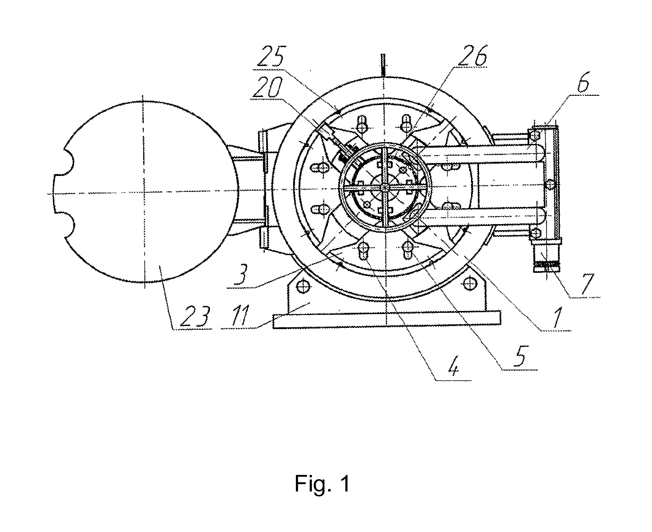
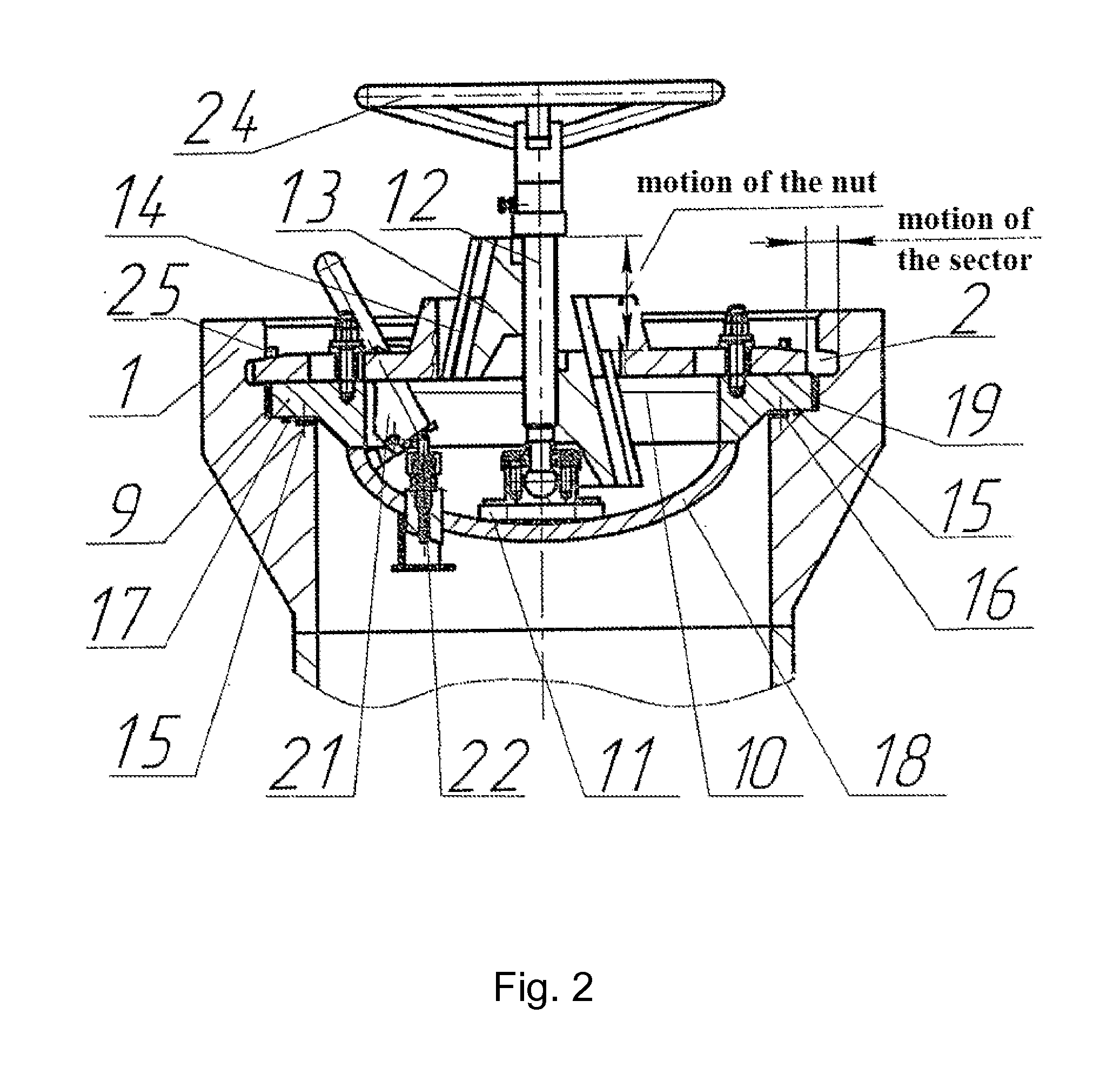
[0011]A gate comprises a pipe 1 (FIGS. 1, 2) with a recess 2, sectors 3 with slots 4 for guiding-arresting bolts 5, a hinge 6 with adjusting-fastening bolts 7 and a lid 8 (FIG. 2) with a flange 9, a supporting ring 10 with a sleeve 11, a screw 12, a nut 13 with T-slots 14, a sealing ring 15 and a gasket 16, recesses 17 and 18 of the pipe 1 for the sealing ring 15 and the gasket 16, a recess 19 for the flange 9, a locking plate 20 (FIG. 1) with a lever 21, a hydraulic cylinder rod 22, a casing 23, a flywheel 24, control markers 25 and T-shaped tenons 26.

[0012]A gate operates as follows.

[0013]After having been attached to a pipe 1 and adjusted by means of a bolting 7 under conditions of a manufacturing plant, a turning lid of the gate comprising a bottom 8, a flange 9 and a hinge 6 is closed by rotating around the hinge 6 using a handle (not shown in figures) and set with the flange 6 into a recess 19 of a pipe 1. In so doing, a sealing ring 15 and a gasket 16 are pressed with the fla...


PUM


Abstract

The invention can be used in pipelines, any devices, man holes and arrangements, at any pressures and working conditions for closable large-diameter pipes. The aim of said invention is to improve the operating reliability of a gate. The inventive gate comprises a lid consisting of a flange and a bottom caved in a pipe, wherein a sleeve provided with a supporting ring is welded to the bottom, arresting elements in the form of sectors insertable into the circular boring of the tube, when they are radially displaced on the flange along clamping bolts and on the supporting ring by the action of the inclined face of a drive nut, are arranged on the end face of the flange and on the supporting ring. The nut is embodied in the form of a truncated pyramid provided with T-slots embodied on the side surfaces thereof. The sectors are provided with T-shaped tenons enabling the sectors to be moved along the end surfaces of strengthening ribs, control markers are mounted on the sectors, a locking plate which, is provided with a lever, descends into a gap embodied between the sectors and locks them by the action of a pneumatic cylinder in the presence of excessive pressure, is arranged inside the lid. The nut can be embodied in the form of a truncated cone. The lid is mounted on articulated joints and the pipe with the lid are covered by an enclosure.

Description

FIELD OF THE INVENTION[0001]The present invention relates to fast-acting gates for pipelines and apparatuses operating under both high and low pressures.BACKGROUND OF THE INVENTION[0002]There is known a gate—a device for locking a lid of a vessel operating under pressure (RU Patent 2249135; IPC F 16 J 13 / 16; claimed Aug. 18, 2003; published Mar. 27, 2005, Bulletin of Inventions No. 9), comprising: a lid with a mechanism for lifting thereof, said lid being installed on a body; a fast-disconnect conical-flanged joint; a lid-closing mechanism, said conical-flanged joint being made in the form of flanges of the body and the lid with a conical outer surface; and a separating device embracing ends of said flanges, said device being embodied to the shape of a pair of clips with a responsive conical drill through. Said lid-closing mechanism is provided with two hydraulic cylinders, whereas said lid-lifting mechanism is provided with a hydraulic jack, a gasket between a flange of the body an...

Claims


Application Information

Patent Timeline
IPC IPC(8): F16J13/16
CPCB65D90/10F16L55/115F16J13/18F16J13/08Y10T292/216F16J13/16
InventorKHASANOV, ILMER YUSUPOVICHGLUKHOVTSEVA, SNEZHANNA VYACHESLAVOVNACHERNIKH, YURY ALEXEEVICHSURIKOV, VITALY IVANOVICHSABIROV, ULFAT NURLYGAYANOVICH
OwnerKHASANOV ILMER YUSUPOVICH