
LED light module

a technology of led light and led light, applied in the direction of fixed installation, semiconductor devices for light sources, light and heating apparatus, etc., can solve the problem of not intended summary, and achieve the effect of improving serviceability

Inactive Publication Date: 2012-08-30
VAN HORN JOHN D +3
View PDF3 Cites 30 Cited by
  • Summary
  • Abstract
  • Description
  • Claims
  • Application Information

AI Technical Summary

Benefits of technology

[0009]A further object of the invention is to provide a unique LED light module wherein a module consisting of an LED panel, heat sink and power supply which are secured together, may be inserted into the case of the LED module and removed therefrom as a single unit which enhances serviceability in both the manufacturing process and in the field.

Problems solved by technology

Moreover, this Summary is not intended for use as an aid in determining the scope of the claimed subject matter.

Method used


Image

  • LED light module
  • LED light module
  • LED light module

Examples


Embodiment Construction

[0034]Embodiments are described more fully below with reference to the accompanying figures, which form a part hereof and show, by way of illustration, specific exemplary embodiments. These embodiments are disclosed in sufficient detail to enable those skilled in the art to practice the invention. However, embodiments may be implemented in many different forms and should not be construed as being limited to the embodiments set forth herein. The following detailed description is, therefore, not to be taken in a limiting sense in that the scope of the present invention is defined only by the appended claims.

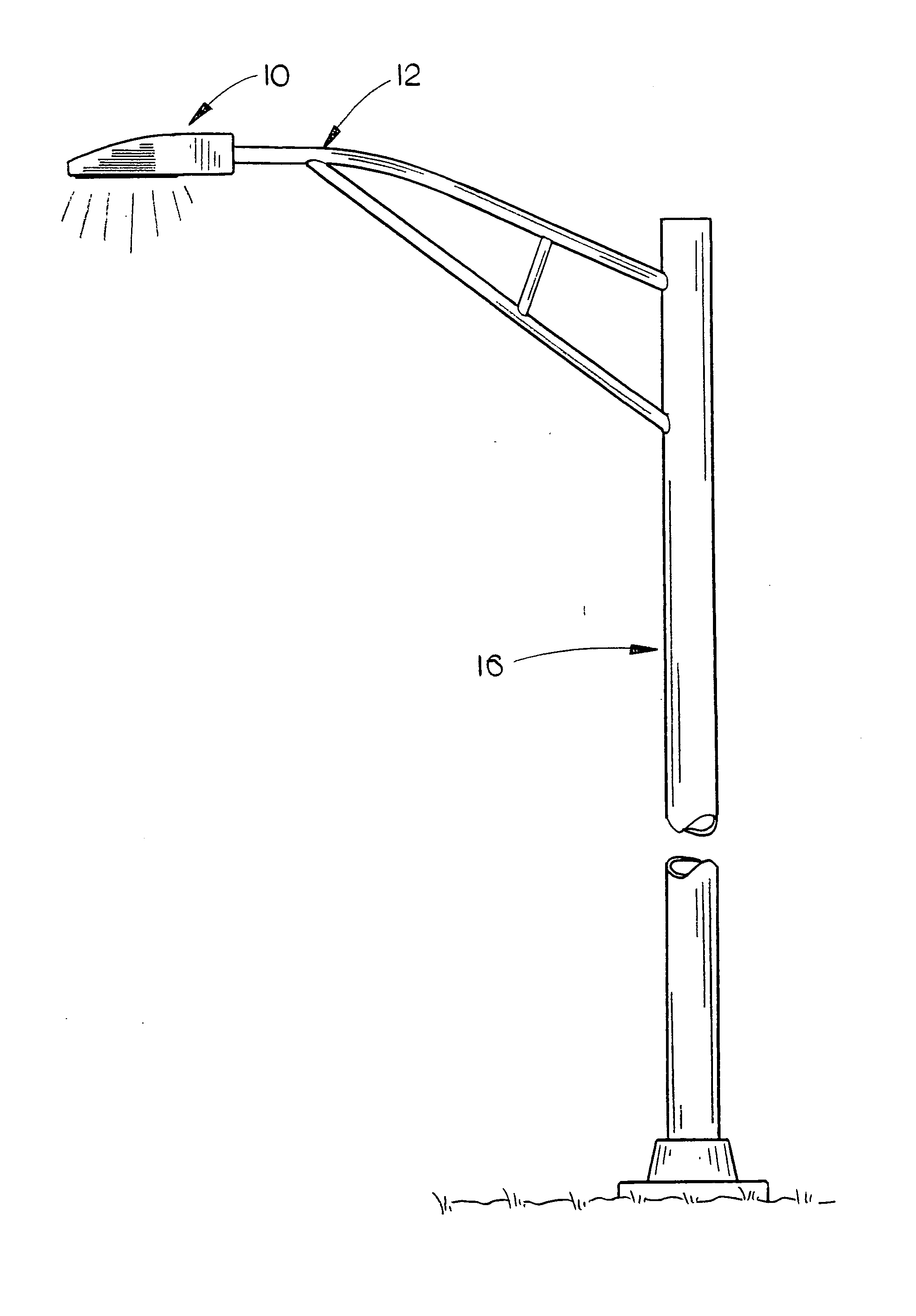
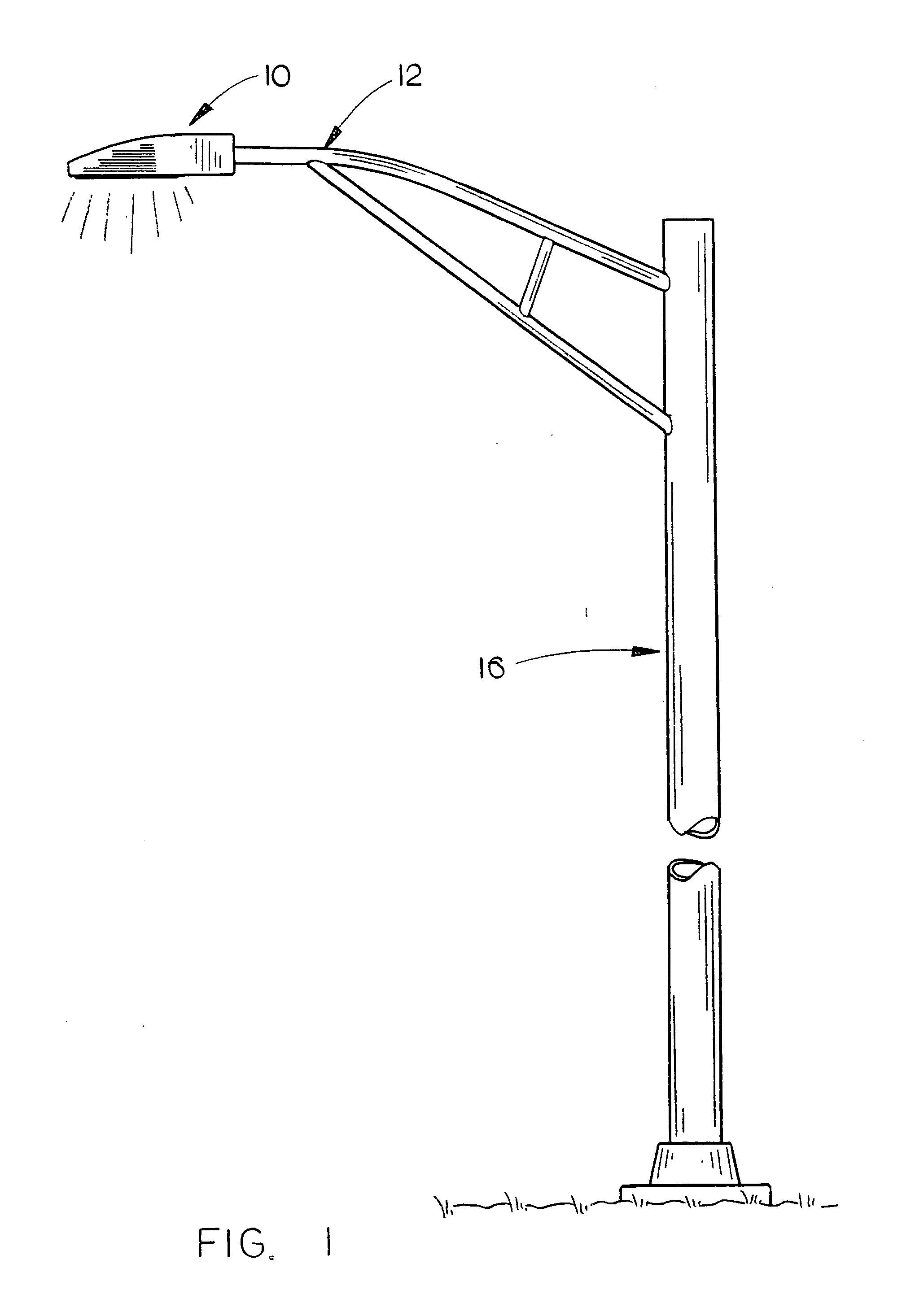
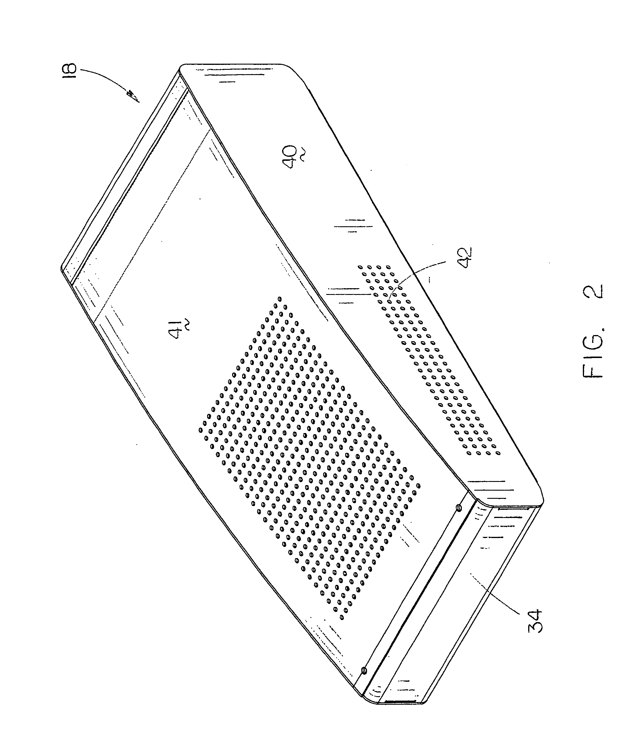
[0035]The numeral 10 refers to an LED light module of this invention which is designed to be secured to a tubular support arm 12 adjacent the outer end 14 thereof. Support arm 12 extends from a support pole 16, as seen in FIG. 1. LED light module 10 generally includes a case or housing 18, clamp assembly 20, heat sink assembly 22, power supply 24 and an LED panel 26. Case 18 is con...


PUM


Abstract

An LED light module for attachment to the outer end of a support arm extending from a support pole is disclosed. The LED light module includes a case having a clamp assembly secured thereto which is adapted to be clamped onto the outer end of the support arm. A module consisting of an LED panel, heat sink and power supply is selectively removably secured to the case as a unit or module so that the unit or module may be inserted into the case as a single unit or removed from the case as a single unit. The heat sink of the invention is comprised of a pair of heat sink members secured together. The power supply is secured to the heat sink at one end thereof with the LED panel secured to the bottom of the heat sink.

Description

BACKGROUND OF THE INVENTION[0001]1. Field of the Invention[0002]This invention relates to a LED light module for attachment to the outer end of a support arm which extends laterally from a support pole.[0003]2. Description of the Related Art[0004]Many types of light modules have been previously provided which are attached to the outer end of a support arm extending from a support pole. In recent years, the incandescent and mercury vapor light modules have been replaced with LED light modules. Generally speaking, most of the prior art LED light modules include a case or housing which houses an LED panel, a heat sink, a power supply and some means to attach the LED module to the outer end of the support arm. Although the prior art LED light modules do perform quite satisfactorily, they suffer from certain shortcomings or disadvantages. Usually, it is desirable to position the light module in a horizontally disposed position. If the outer end of the support arm is not horizontally disp...

Claims


Application Information

Patent Timeline
Patent Type & Authority Applications(United States)
IPC IPC(8): F21V15/01F21V29/00
CPCF21S8/086F21Y2105/001F21V23/02F21V29/2212F21W2131/103F21V17/002F21Y2105/10F21Y2115/10
Inventor VAN HORN, JOHN D.GRANT, JR., RICHARD I.LEPAGE, CHRISTOPHER M.KEMPF, RANDY J.
Owner VAN HORN JOHN D
Learn More