Front end structure of vehicle

a technology for front end structures and vehicles, which is applied in the direction of machines/engines, transportation and packaging, light and heating equipment, etc., can solve the problems and achieve the effect of reducing the heat-exchange performance of the heat-exchanger and improving serviceability

Active Publication Date: 2006-12-19
DENSO CORP
View PDF11 Cites 32 Cited by
  • Summary
  • Abstract
  • Description
  • Claims
  • Application Information

AI Technical Summary

Benefits of technology

[0007]The present invention is made in view of the foregoing matters, and it is an object of the present invention to provide a vehicle front end structure capable of increasing serviceability. It is another object of the present invention to provide a vehicle front end structure capable of restricting a decrease in a heat-exchanging performance of a heat exchanger due to air leakage through a gap between a front end panel and a fan shroud.
[0009]Accordingly, even if the front end panel and the fan shroud are provided as separate parts, air leakage through the gap between the front end panel and the fans shroud is restricted by the labyrinthine gap structure. Therefore, a decrease in a heat-exchanging performance of the heat exchanger is restricted. Also, the front end panel and the fan shroud are separately or independently exchanged or repaired when the part is broken such as due to a vehicle collision. Accordingly, serviceability is improved.

Problems solved by technology

Therefore, a decrease in a heat-exchanging performance of the heat exchanger is restricted.

Method used


Image

  • Front end structure of vehicle
  • Front end structure of vehicle
  • Front end structure of vehicle

Examples


first embodiment

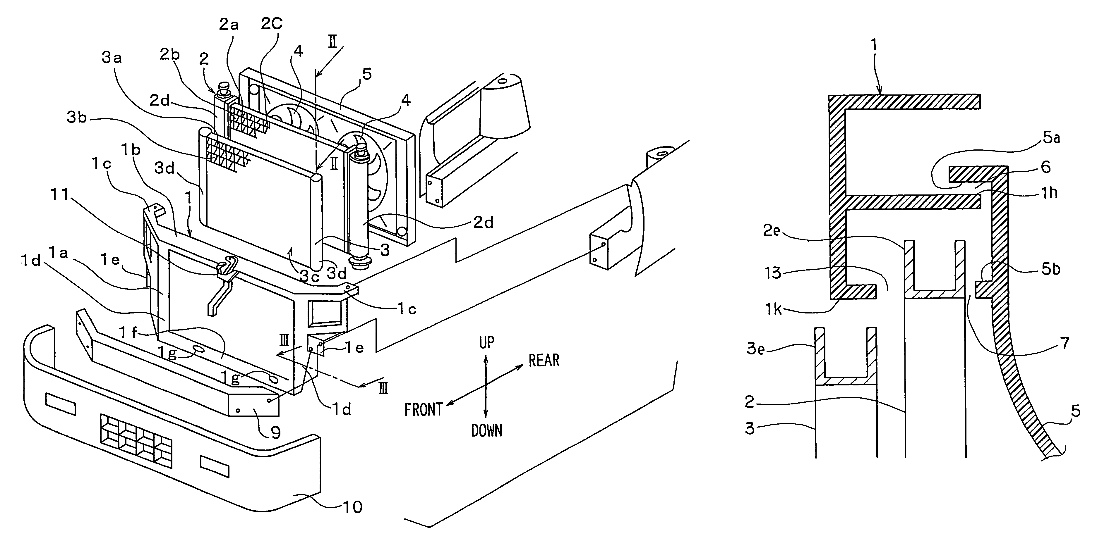
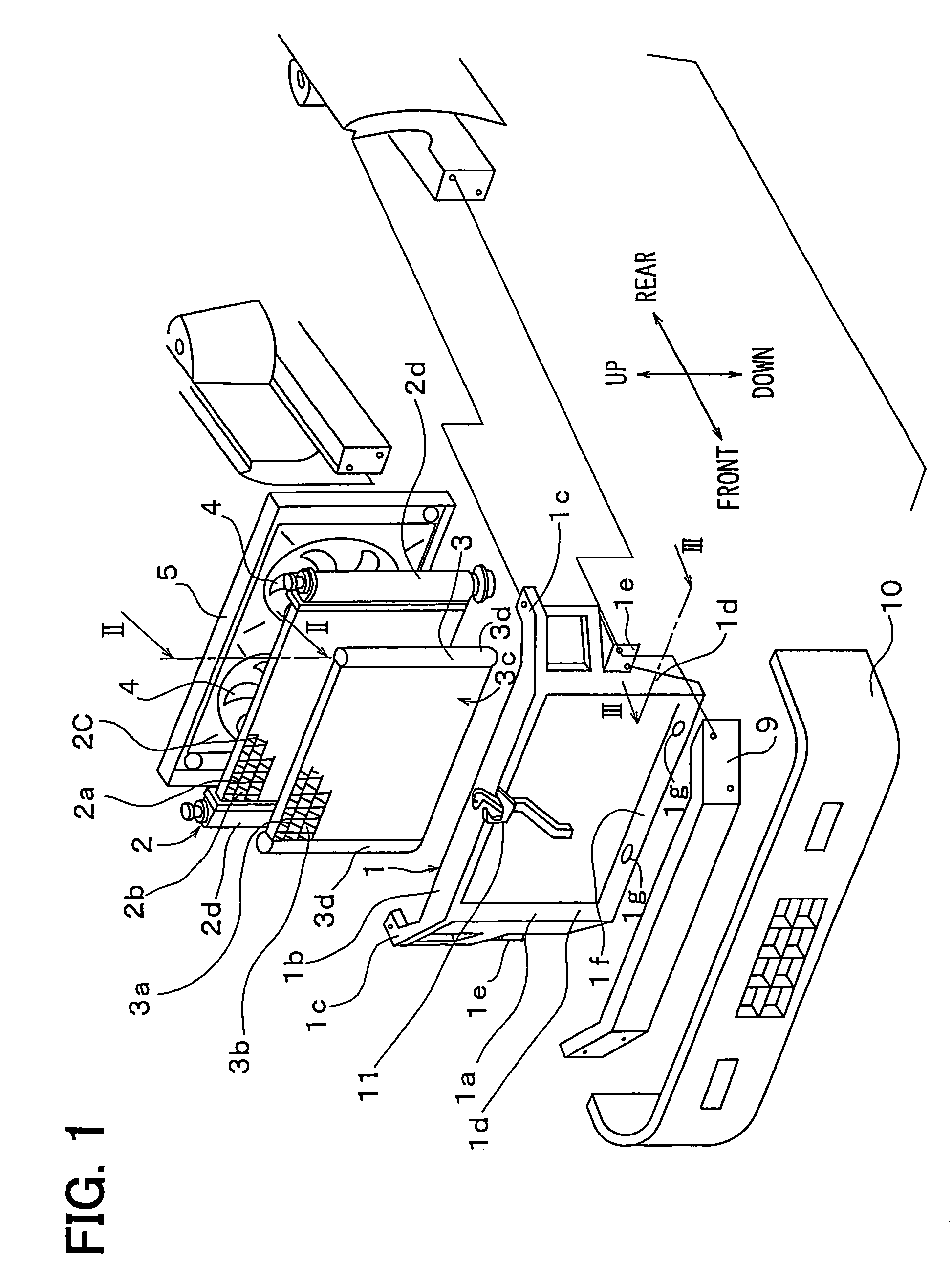
[0018]Referring to FIG. 1, a front end panel 1 is fixed to a vehicle body at a vehicle front end. The front end panel 1 generally extends in a vehicle right and left direction (vehicle width direction). The front end panel 1 includes a frame portion 1a, first fixing portions 1c and second fixing portions 1e. The frame portion 1a has a substantially rectangular shape. The first fixing portions 1c extend from longitudinal ends of an upper beam portion 1b of the frame portion 1a toward a side body of the vehicle. The second fixing portions 1e are formed on side pillar portions 1d of the frame portion 1a.

[0019]Further, radiator fixing portions 1g for fixing a radiator 2 are formed on the upper beam portion 1b and a lower beam portion 1f of the frame portion 1a. The radiator 2 is elastically supported by the front end panel 1 through an elastic supporting member (not shown) such as a rubber vibration insulator, which is elastically deformable. In the embodiment, the frame portion 1a, th...

second embodiment

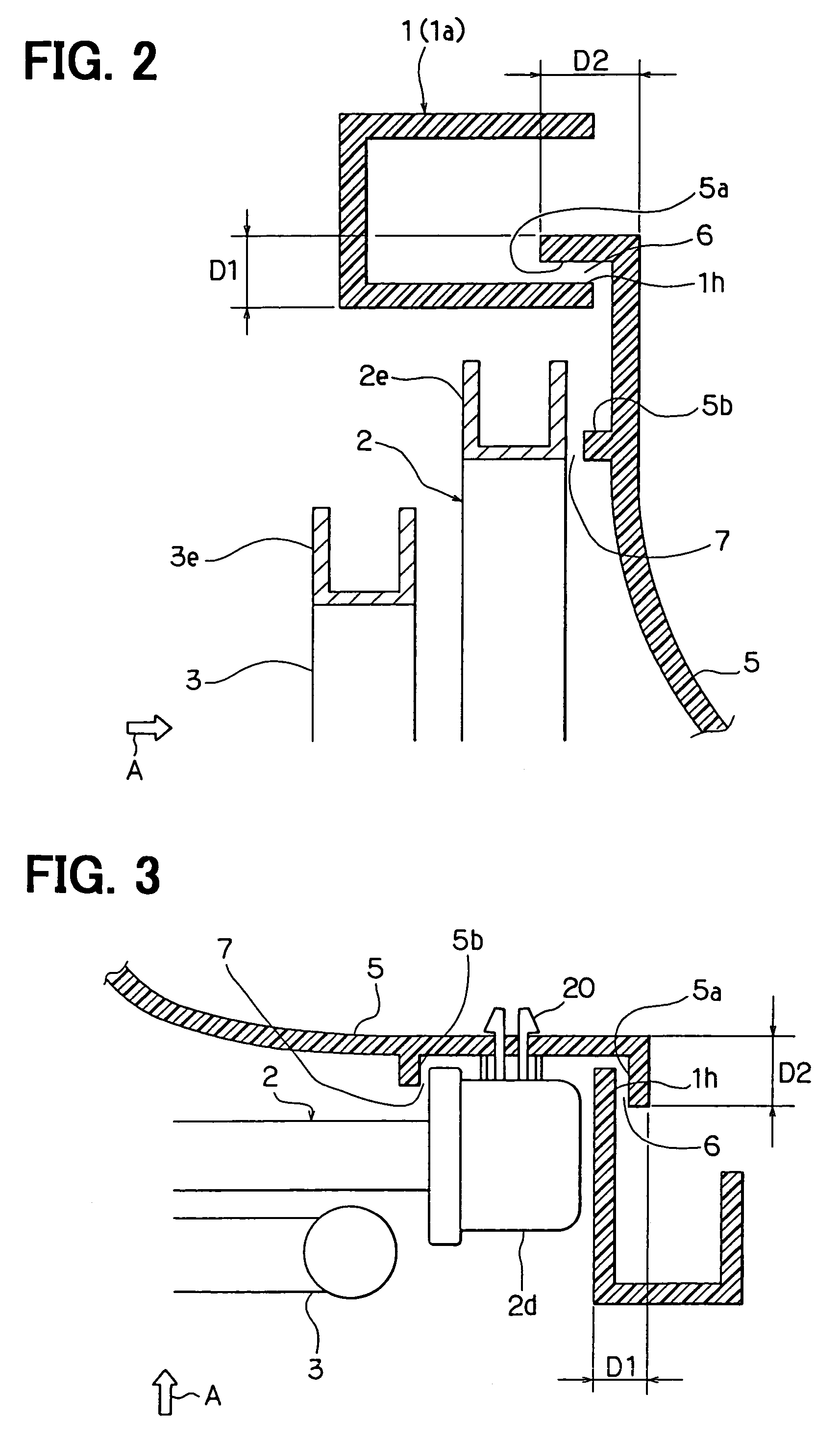
[0035]Referring to FIGS. 4 to 6, the opposing shroud portion 5a is formed at the positions other than the position corresponding to the header tanks 2d of the radiator 2. That is, the opposing shroud portion 5a is formed at positions corresponding to the side plates 2e of the radiator 2.

[0036]The labyrinthine gap structure 6, which is constructed by the opposing panel portion 1h and the opposing shroud portion 5a, is not formed at the positions corresponding to the header tanks 2d of the radiator 2. Instead, the front end panel 1 forms a sealing projection (second panel projection) 1j to define a labyrinthine gap 12 between the header tank 2d and the front end panel 1, as shown in FIG. 6.

[0037]Further, as shown in FIG. 5, the front end panel 1 forms a sealing projection (first panel projection) 1k at a position corresponding to the side plate 2e on a front side of the radiator 2, that is, on a side opposite to the fan shroud 5 with respect to the radiator 2. The sealing projection 1...


PUM


Abstract

In a front end structure of a vehicle, a front end panel and a fan shroud are provided as separate parts. The front end panel and the fan shroud form labyrinthine gap structure between them. The labyrinthine gap structure restricts air from leaking or entering through a space between the front end panel and the fan shroud. Accordingly, a heat exchanging performance of a heat exchanger is not decreased. Also, the front end panel and the fan shroud are separately exchangeable or repairable.

Description

CROSS REFERENCE TO RELATED APPLICATION[0001]This application is based on Japanese Patent Application No. 2003-120434 filed on Apr. 24, 2003, the disclosure of which is incorporated herein by reference.BACKGROUND OF THE INVENTION[0002]1. Field of the Invention[0003]The present invention relates to a front end structure of a vehicle.[0004]2. Related Art[0005]At the front end of a vehicle, a radiator and a condenser are elastically supported by a front end panel. A vehicle front end structure of Unexamined Japanese Patent Publication No. JP-A-2003-127903, it is proposed to form a labyrinthine gap structure between the radiator and the front end panel. Also, the front end panel is integrally formed with a shroud surrounding a fan. The labyrinthine gap structure is provided by an opposing panel portion formed on the front end panel at a position opposing an outer peripheral portion of the radiator and an opposing radiator portion formed on the radiator at a position opposing the opposing...

Claims


Application Information

Patent Timeline
Patent Type & Authority Patents(United States)
IPC IPC(8): B60K11/04B62D25/08F01P11/10
CPCB62D25/084F01P11/10F01P2070/50
Inventor SASANO, NORIHISAKUNIKATA, YUHEI
Owner DENSO CORP
Why Eureka
Try Eureka