

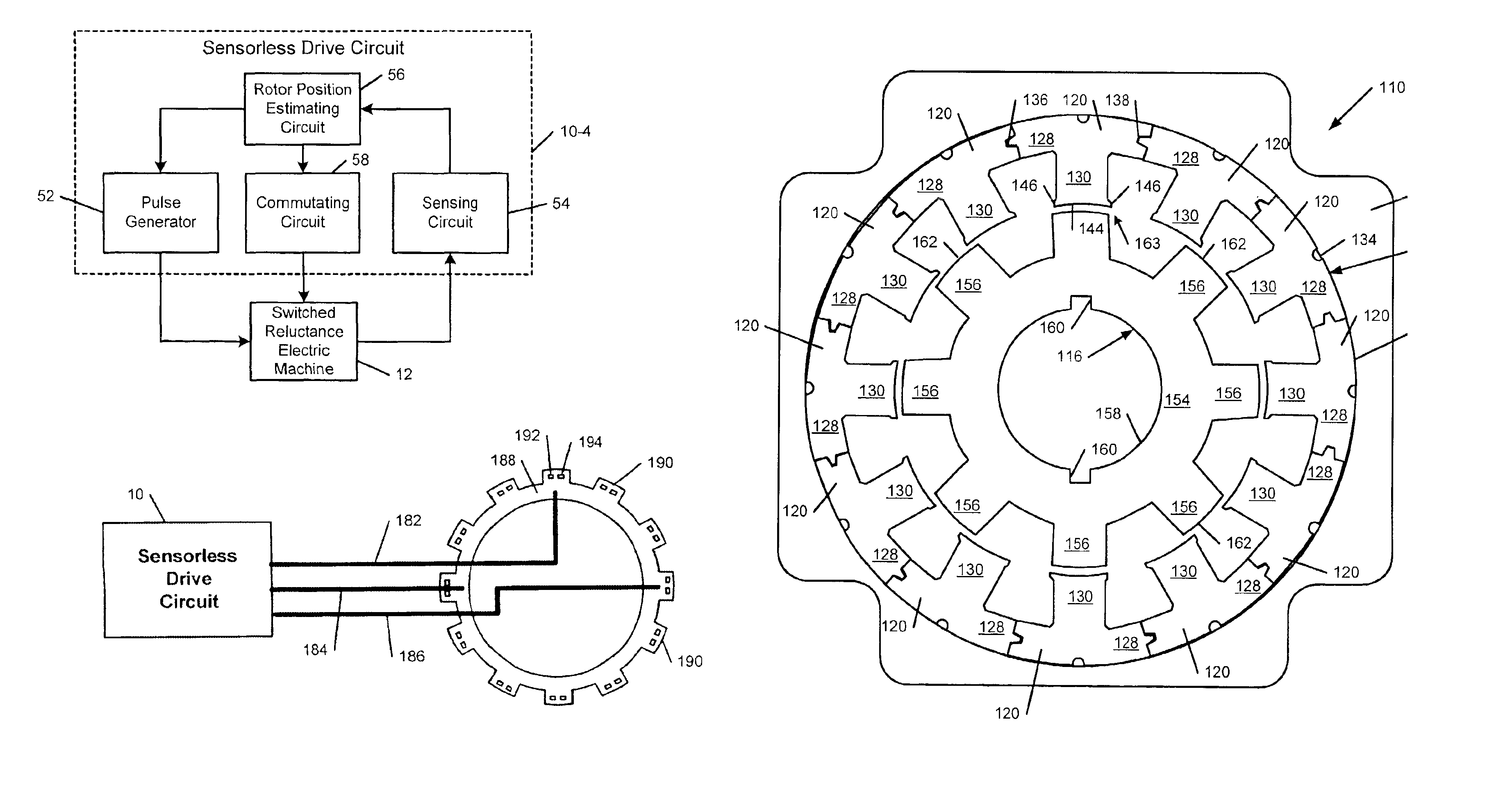
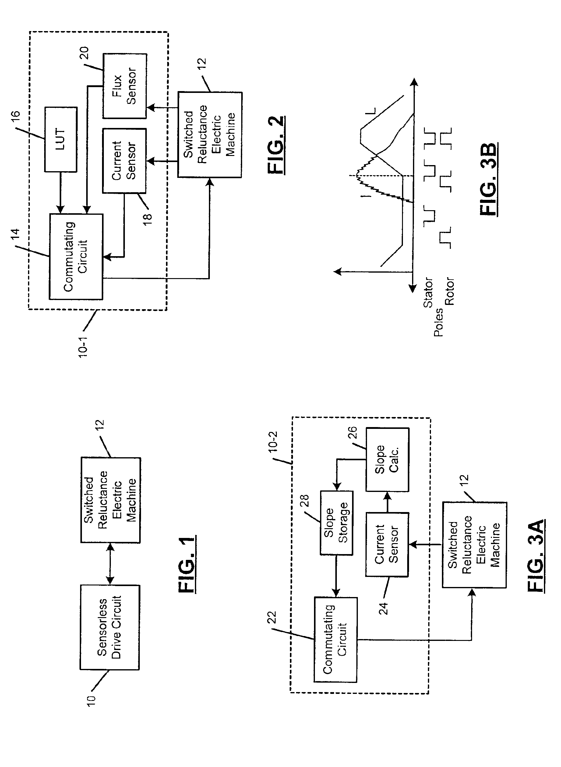
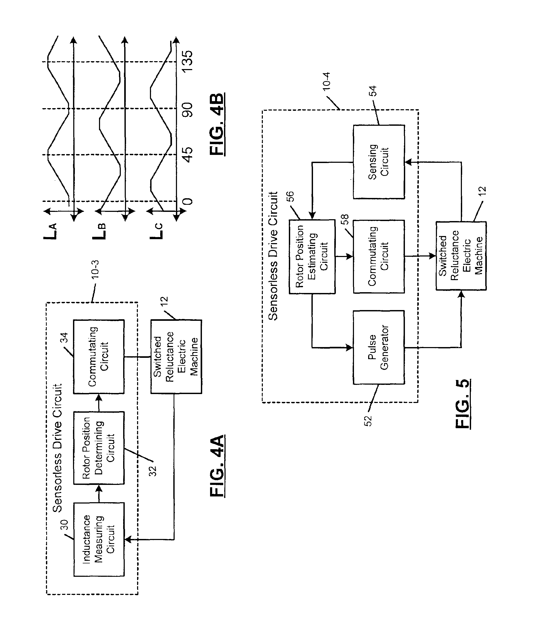
Sensorless switched reluctance electric machine with segmented stator
a segmented technology, applied in the direction of motor/generator/converter stopper, dynamo-electric converter control, etc., can solve the problems of degrading the performance of the electric machine, the rotor torque will vary, and the machine will not operate at the optimal efficiency, so as to improve the torque density of the switched reluctance electric machine, reduce the creep of the winding during use, and facilitate the winding process
- Summary
- Abstract
- Description
- Claims
- Application Information
AI Technical Summary
Benefits of technology
Problems solved by technology
Method used
Image

Examples
Embodiment Construction
[0045]The following detailed description provides preferred exemplary embodiments only and is not intended to limit the scope, applicability or configuration of the present invention. Rather, the detailed description of the preferred exemplary embodiments will provide those skilled in the art with an enabling description for implementing the preferred exemplary embodiments of the present invention. It will be understood that various changes may be made in the function and arrangement of the elements without departing from the spirit and scope of the invention as set forth in the appended claims.
[0046]The stator of the switched reluctance electric machine according to the present invention has highly uniform electrical characteristics. The segmented stator and the end cap assembly according to the invention allow more precise winding of the stator poles and retention of the windings during use. As a result of the more uniform electrical characteristics, sensorless measurement techniq...
PUM
 Abstract
Description
Claims
Application Information