Segmented stator switched reluctance machine

a segmented technology, applied in the direction of motor/generator/converter stopper, dynamo-electric converter control, etc., can solve the problems of degrading the performance of the electric machine, the constant torque of the rotor cannot be maintained, and the machine cannot operate at an optimal efficiency, so as to improve the torque density of the switched reluctance electric machine, reduce the creep of winding during use, and facilitate the winding process

Inactive Publication Date: 2002-09-12
NIDEC MOTOR CORP
View PDF25 Cites 50 Cited by
  • Summary
  • Abstract
  • Description
  • Claims
  • Application Information

AI Technical Summary

Benefits of technology

0021] According to other features of the invention, each stator plate has an outer rim section and a tooth section. The end cap assembly includes a pair of end caps that are secured to opposite ends of the stator segment core, and a pair of retainer plates interconnecting the end caps on opposite sides of the stator segment core. The end cap assembly defines an annular retention channel within which the winding wire is wound. The retention channel facilitates improved precision in the winding process and tends to reduce winding creep during use.
0022] By providing a segmented stator, the present invention improves the torque density of the switched reluctance electric machine. As a result, the torque output of the switched reluctance electric machine can be increased and / or the dimensions of the switched reluctance electric machine can be reduced for a given torque output. In addition, the stator segment assemblies can be manufactured with a greater uniformity and with lower variations in inductance and resistance. Sensorless rotor position sensing techniques can be employed to dramatically lower the manufacturing costs of the switched reluctance machine and to improve reliability in the field.

Problems solved by technology

If the active stage is initiated and / or commutated too early or too late with respect to the position of the rotor, a constant torque on the rotor will not be maintained and the machine will not operate at an optimum efficiency.
Misalignment of the sensor board is known to degrade the performance of the electric machine.
Unfortunately, utilization of these complex alignment techniques increases the manufacturing costs for switched reluctance electric machines equipped with RPTs.
The RPTs also increase the overall size of the switched reluctance electric machine, which can adversely impact machine and product packaging requirements.
The costs of the RPTs often place switched reluctance electric machines at a competitive disadvantage in applications that are suitable for open-loop induction electric machines that do not require RPTs.
Another drawback with RPTs involves field servicing of the switched reluctance electric machines.
Specifically, wear elements, such as the bearings, that are located within the enclosed rotor housing may need to be repaired or replaced.
Because alignment of the sensor board is important, replacement of the end shield often requires the use of complex realignment techniques.
When the service technician improperly performs the alignment techniques, the sensor board is misaligned and the motor's performance is adversely impacted.
When sensing the angular rotor position using the "sensorless" approach, variations in the electrical characteristics of the individual stator pole windings can adversely impact the ability of the sensorless drive circuits to correctly derive the angular rotor position.
If the resistance and / or inductance varies from one stator winding to another, the drive circuit may incorrectly determine the angular rotor position.
Winding creep and other assembly variations also impact the inductance and resistance of the winding wire over time, which makes it difficult to accurately perform "sensorless" control due to the non-conformity of the salient stator poles.
It is difficult to hold the winding wire in place during wrapping and forming of the windings.
This is particularly true for salient stator poles of reluctance machines that typically have teeth with parallel sides that do not hold the winding wire very well.
However, as the size of the tangs increases and the slot opening dimension decreases, it becomes more difficult or impossible to employ the conventional needle and transfer winding methods.
Widening of the tangs may also compromise performance.

Method used


Image

  • Segmented stator switched reluctance machine
  • Segmented stator switched reluctance machine
  • Segmented stator switched reluctance machine

Examples


Embodiment Construction

[0035] The following detailed description provides preferred exemplary embodiments only and is not intended to limit the scope, applicability or configuration of the present invention. Rather, the detailed description of the preferred exemplary embodiments will provide those skilled in the art with an enabling description for implementing the preferred exemplary embodiments of the present invention. It will be understood that various changes may be made in the function and arrangement of the elements without departing from the spirit and scope of the invention as set forth in the appended claims.

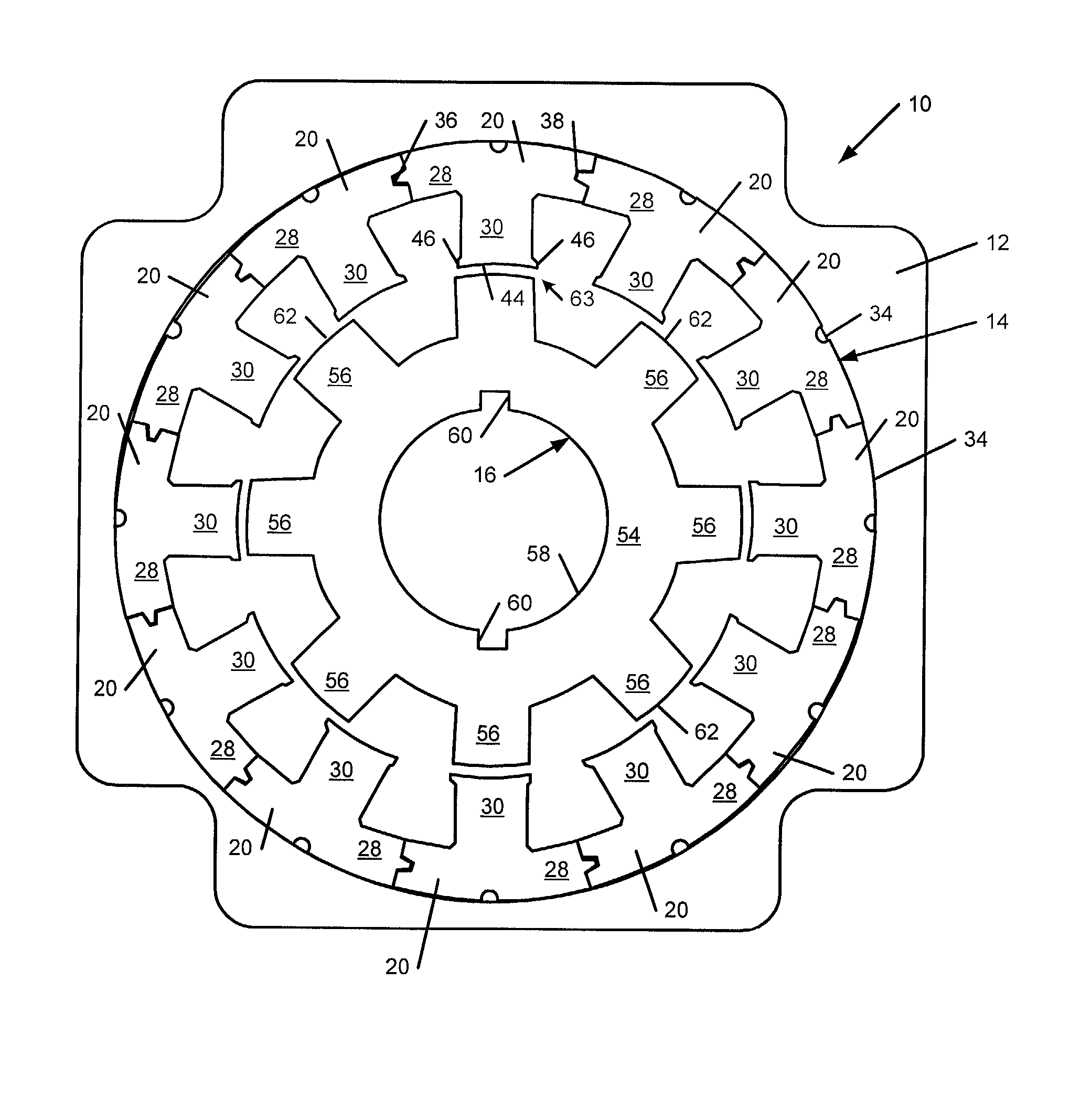
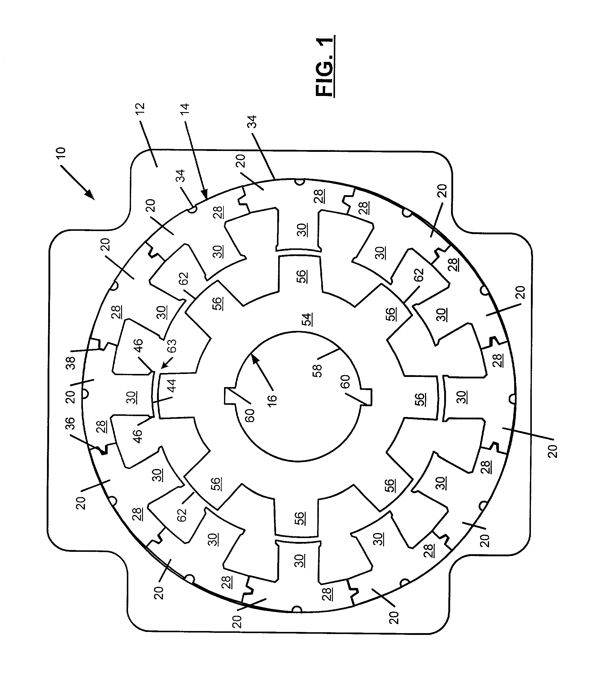
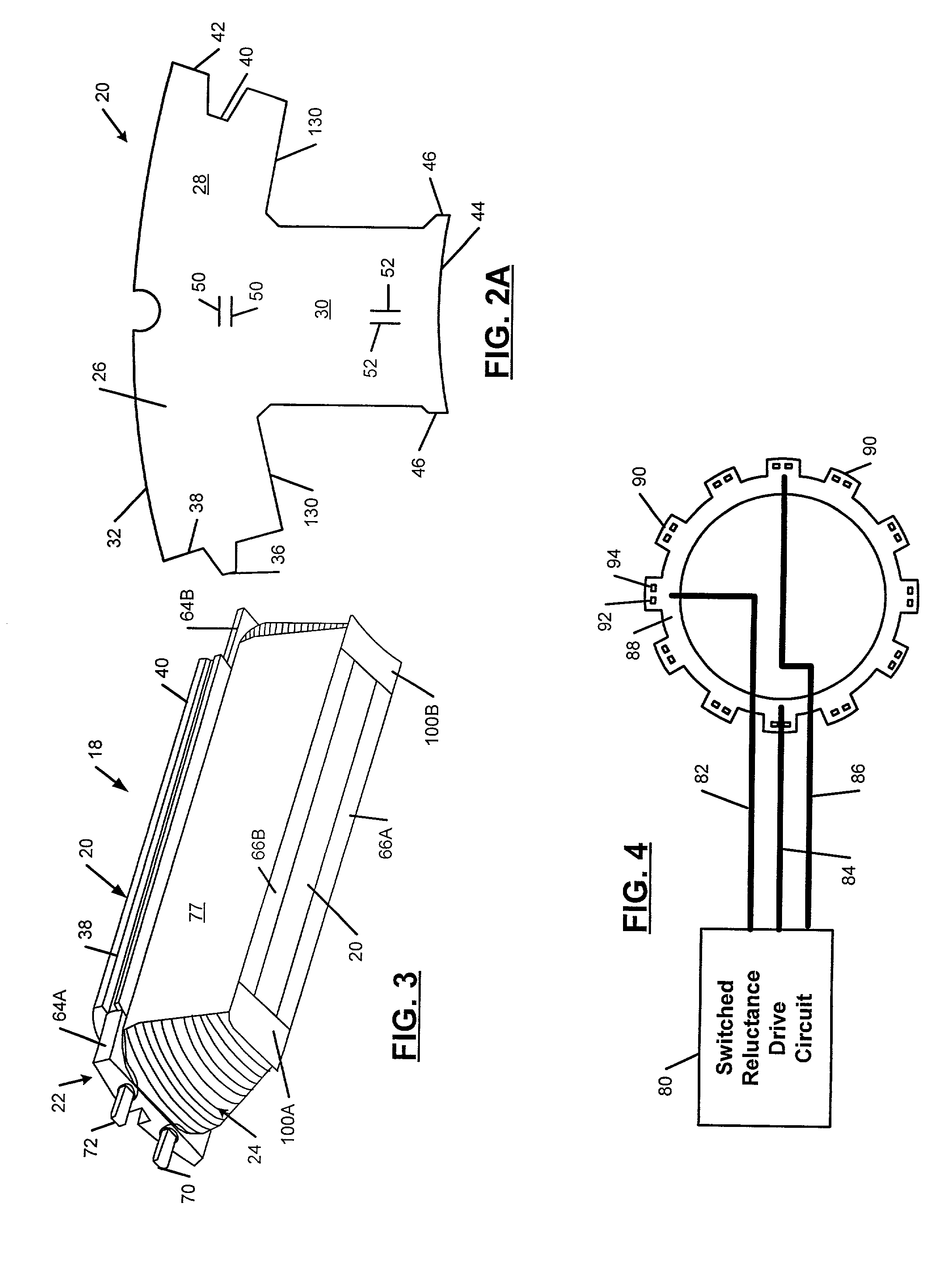
[0036] Referring now to the drawings, a switched reluctance machine 10 is shown to include a housing 12, a segmented stator 14 mounted in the housing 12, and a rotor 16 supported for rotation relative to the segmented stator 14. In accordance with the present invention, the segmented stator 14 includes a plurality of stator segment assemblies 18 that can be individually assembled and then co...


PUM


Abstract

A switched reluctance machine includes a stator with a plurality of circumferentially-spaced stator segment assemblies that include salient stator poles and inter-polar stator slots. Each of the stator segment assemblies includes a stack of stator plates forming a stator segment core, an end cap assembly, and winding wire wound around the stator segment core and the end cap assembly. The rotor defines a plurality of rotor poles. The rotor tends to rotate relative to the stator to maximize the inductance of an energized winding. A drive circuit energizes the winding wire around the stator segment assemblies based on a rotational position of the rotor. Each stator plate includes a first radially outer rim section and a tooth section that extends radially inwardly from a first center portion of the first radially outer rim section.

Description

FIELD OF THE INVENTION[0001] This invention relates to electric machines and, more particularly, to a switched reluctance electric machine including a segmented stator.BACKGROUND OF THE INVENTION[0002] Reluctance electric machines, such as motors and generators, typically include a stator that is mounted inside a machine housing and a rotor that is supported for rotation relative to the stator. Reluctance electric machines produce torque as a result of the rotor tending to rotate to a position that minimizes the reluctance of the magnetic circuit and maximizes the inductance of an energized winding of the stator. A drive circuit generates a set of stator winding currents that are output to stator pole windings and that produce a magnetic field. In response to the magnetic field, the rotor rotates in an attempt to maximize the inductance of the energized winding of the stator.[0003] In synchronous reluctance electric machines, the windings are energized at a controlled frequency. Con...

Claims


Application Information

Patent Timeline
Patent Type & Authority Applications(United States)
IPC IPC(8): H02K1/14H02K3/52H02K19/10
CPCH02K1/148H02K3/522H02K19/103H02K2201/15
Inventor PEACHEE, C. T.WILLIAMS, DONALD J.WAFER, JAMES A.PIRON, MARIELLERANDALL, STEVEN P.WALLACE, RICHARD S. JR.MCCLELLAND, MICHAEL L.
Owner NIDEC MOTOR CORP
Why Eureka
Try Eureka