Turbine Bucket Angel Wing Compression Seal

a technology of compression seal and turbine bucket, which is applied in the direction of liquid fuel engines, vessel construction, marine propulsion, etc., can solve the problems of reducing the cooling capacity of the available cooling air, and affecting the efficiency of the turbine bucket. , to achieve the effect of reducing the cooling air loss of the turbine buck

Active Publication Date: 2010-07-15
GENERAL ELECTRIC CO
View PDF6 Cites 7 Cited by
  • Summary
  • Abstract
  • Description
  • Claims
  • Application Information

AI Technical Summary

Benefits of technology

[0007]The present application further provides a method of reducing turbine bucket cooling air losses. The method may include the steps of positioning an angel wing seal about the bucket, providing a sinusoidal...

Problems solved by technology

A drawback with the angel wing type designs is that the gas path pressure profile may vary circumferentially, particularly downstream of the buckets.
Current angel wing configurations, however, genera...

Method used


Image

  • Turbine Bucket Angel Wing Compression Seal
  • Turbine Bucket Angel Wing Compression Seal
  • Turbine Bucket Angel Wing Compression Seal

Examples


Embodiment Construction

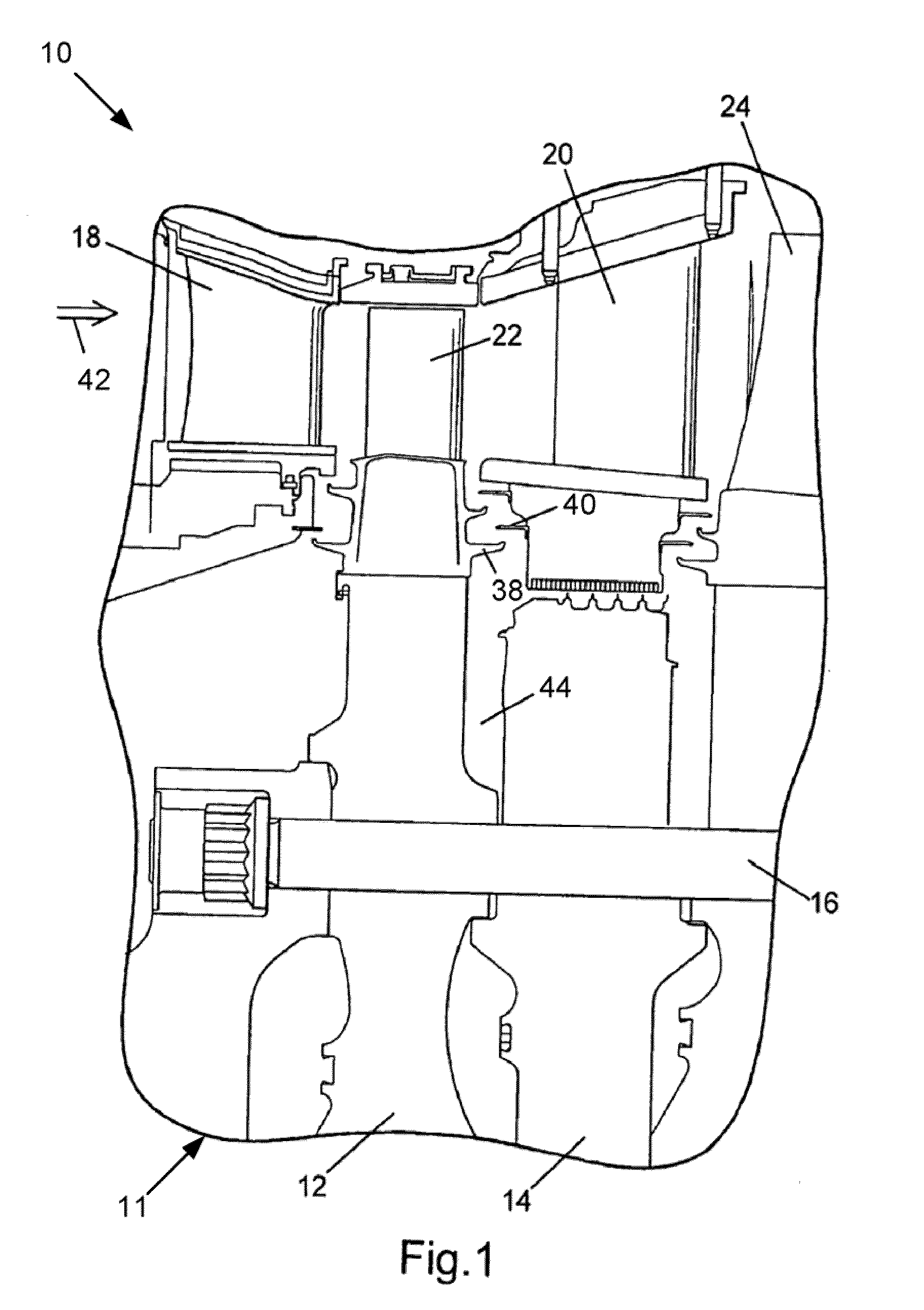
[0016]Referring now to the drawings, in which like numerals refer to like elements throughout the several views, FIG. 1 shows a section of a gas turbine 10. The gas turbine 10 includes a rotor 11 having axially spaced rotor wheels 12 and spacers 14 joined one to the other by a number of circumferentially spaced, axially extending bolts 16. The turbine 10 includes various stages having nozzles, for example, a first stage nozzle 18 and a second stage nozzle 20, with a number of circumferentially spaced stator blades. Between the nozzles 18, 20 and rotating with the rotor 11 are a number of rotor blades, for example, a first stage bucket 22 and a second stage bucket 24.

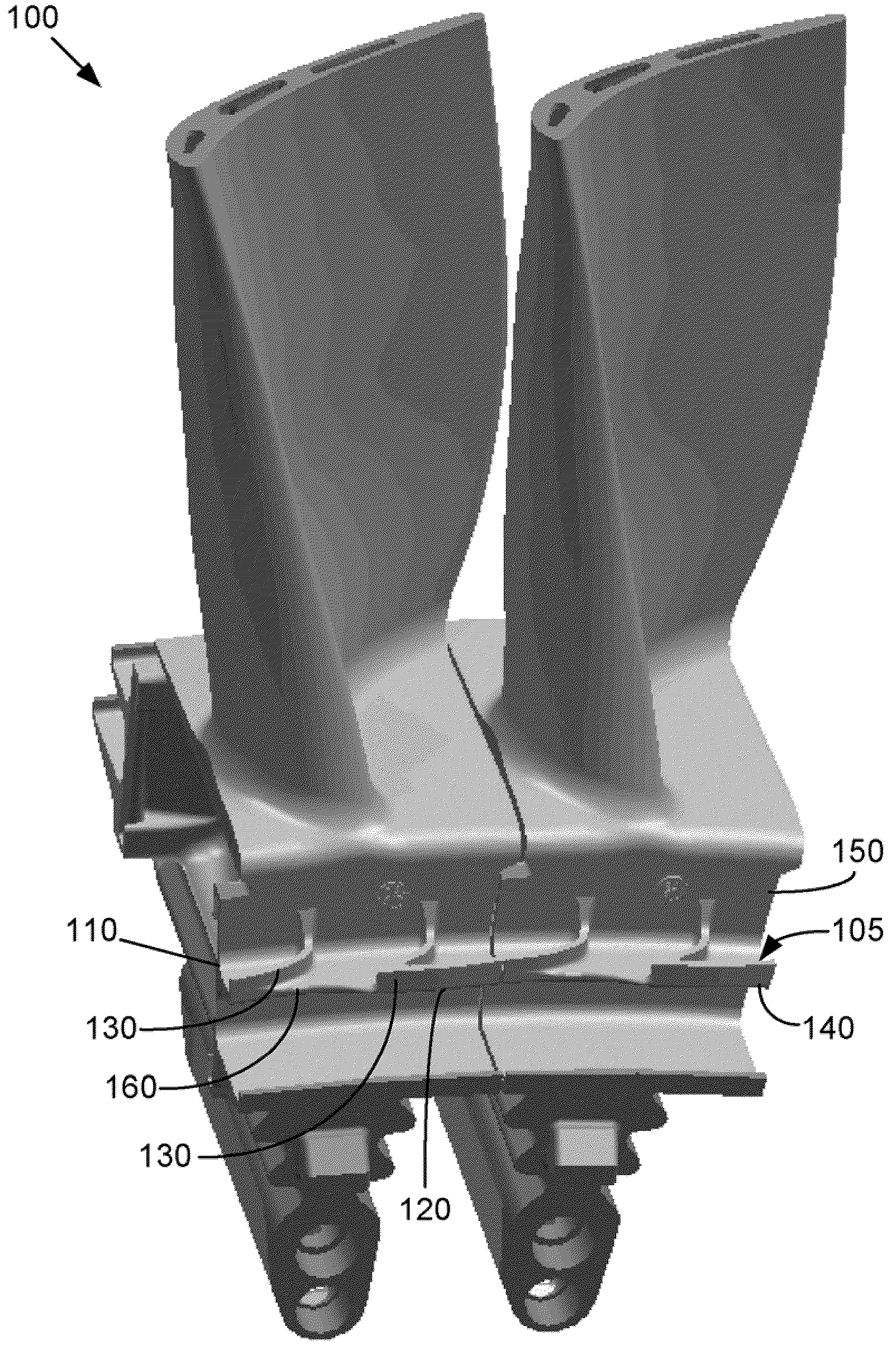
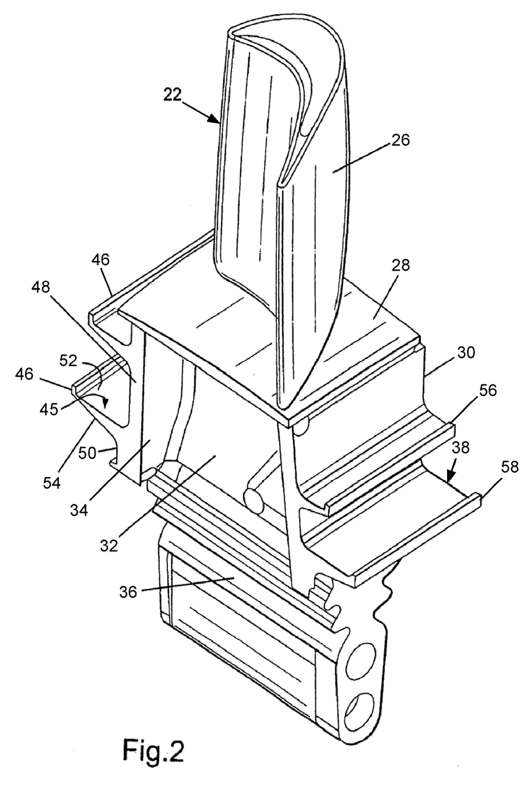
[0017]Referring to FIG. 2, each bucket 22, 24 may include an airfoil 26 mounted on a platform 28 of a shank 30. The shank 30 may have a shank pocket 32 with integral cover plates 34 and a dovetail 36 for connection with the rotor wheel 12. The buckets 22, 24 may be integrally cast. Other components and turbine configurat...


PUM


Abstract

The present application provides an angel wing seal for a turbine bucket. The angel wing seal may include a first wing with a sinusoidally-shaped outer edge and a number of wing teeth positioned thereon.

Description

TECHNICAL FIELD[0001]The present application relates generally to gas turbine engines and more particularly relates to a turbine bucket having an angel wing compression seal with a sinusoidal shape.BACKGROUND OF THE INVENTION[0002]Minimizing secondary cooling air leakage through the wheel spaces may increase overall turbine performance and efficiency. The sealing mechanism should effectively seal between rotating components such as buckets, blades, disks, and spacers and stationary components such as nozzles, vanes, and diaphragms. Specifically, the hot gases flowing through the turbine should be prevented from “ingesting” or leaking into the wheel spaces between the rotating components attached to the rotor and the stationary components attached to the turbine shell.[0003]The wheel space cavities may be pressurized to provide a positive outflow from the wheel spaces into the gas path. Angel wing type seals also may be used to minimize this outflow by restricting the gap through whi...

Claims


Application Information

Patent Timeline
IPC IPC(8): F01D11/00F01D5/14
CPCF05D2250/184F01D11/001
Inventor BULGRIN, CHARLES ALANJACALA, ARIEL CAESAR-PREPENAITZEL, GARY MICHAELBRUNER, RALPH CHRIS
Owner GENERAL ELECTRIC CO
Why Eureka
Try Eureka