Supercharge Your Innovation With Domain-Expert AI Agents!

Pipe support system and method for use in underground pipe ramming

Active Publication Date: 2010-07-22
MPC BEDROCK MONTANA
View PDF3 Cites 14 Cited by
  • Summary
  • Abstract
  • Description
  • Claims
  • Application Information

AI Technical Summary

Benefits of technology

[0005]A skid according to the invention includes a frame which is supported on the ground at the work site. A cradle assembly is mounted on the frame. The cradle assembly includes a cradle suitable for supporting a pipe section by its outer surface and a trough or second frame in which the cradle is slidingly disposed. A vertical jack mechanism is provided on the frame for raising and lowering the cradle assembly, and a horizontal jack mechanism is provided in the second frame for sliding the cradle back and forth. The jack mechanisms are preferably hydraulic cylinders. In a preferred embodiment, a pair of vertical hydraulic cylinders are provided at opposite ends of the frame, which cylinders are connected to opposite ends of the trough or second frame so that the cradle assembly can move up and down within a range of positions determined by the length of the hydraulic pistons.
[0006]According to a method of the invention, a series of skids of the invention are positioned in spaced locations, preferably parallel to one another, to support a pipe section during pipe ramming. A minimum of two skids are used, one each to support the front and rear of the pipe section, and if needed in view of pipe length, a third skid supports the pipe section at its middle. The vertical jacks of the skid mechanisms are operated to raise or lower the cradle assembly and pipe section as needed to achieve a desired position and grade. This is preferably done after a pipe section has been placed on the cradles of the skids, since the weight of the pipe section is likely to cause settling of the skids. If the pipe section needs to be inserted at a desired horizontal angle, one or more of the second hydraulic cylinders are operated to change the side to side angle at which the pipe section is to be inserted at. These and other aspects of the invention are described further in the detailed description which follows.

Problems solved by technology

This is preferably done after a pipe section has been placed on the cradles of the skids, since the weight of the pipe section is likely to cause settling of the skids.

Method used


Image

  • Pipe support system and method for use in underground pipe ramming
  • Pipe support system and method for use in underground pipe ramming
  • Pipe support system and method for use in underground pipe ramming

Examples


Embodiment Construction

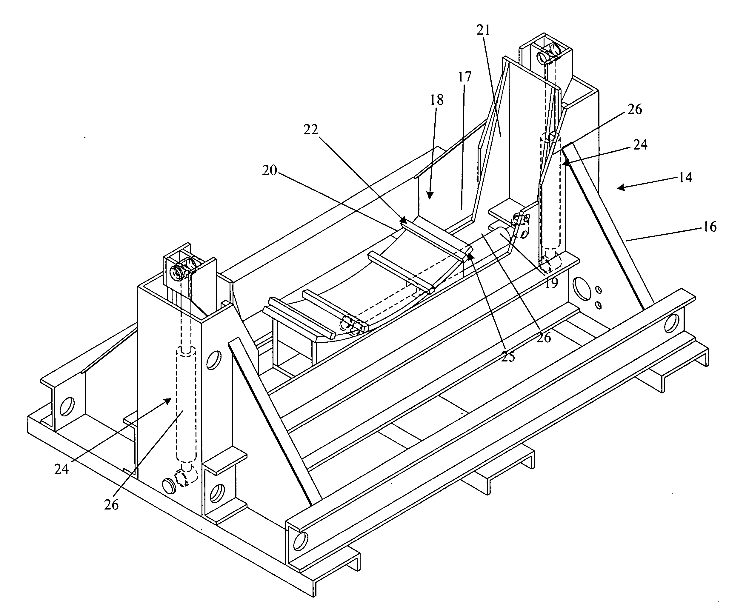
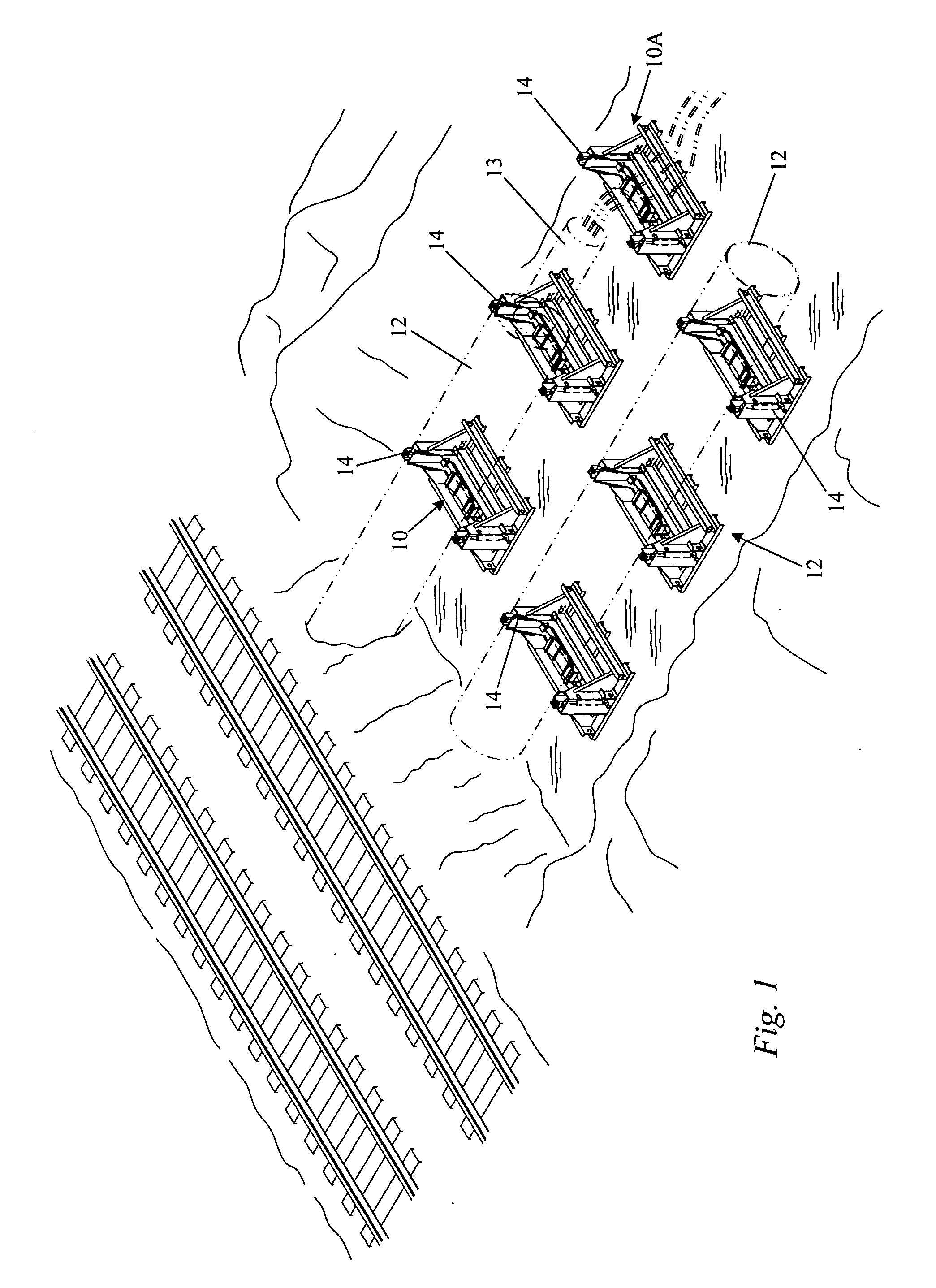
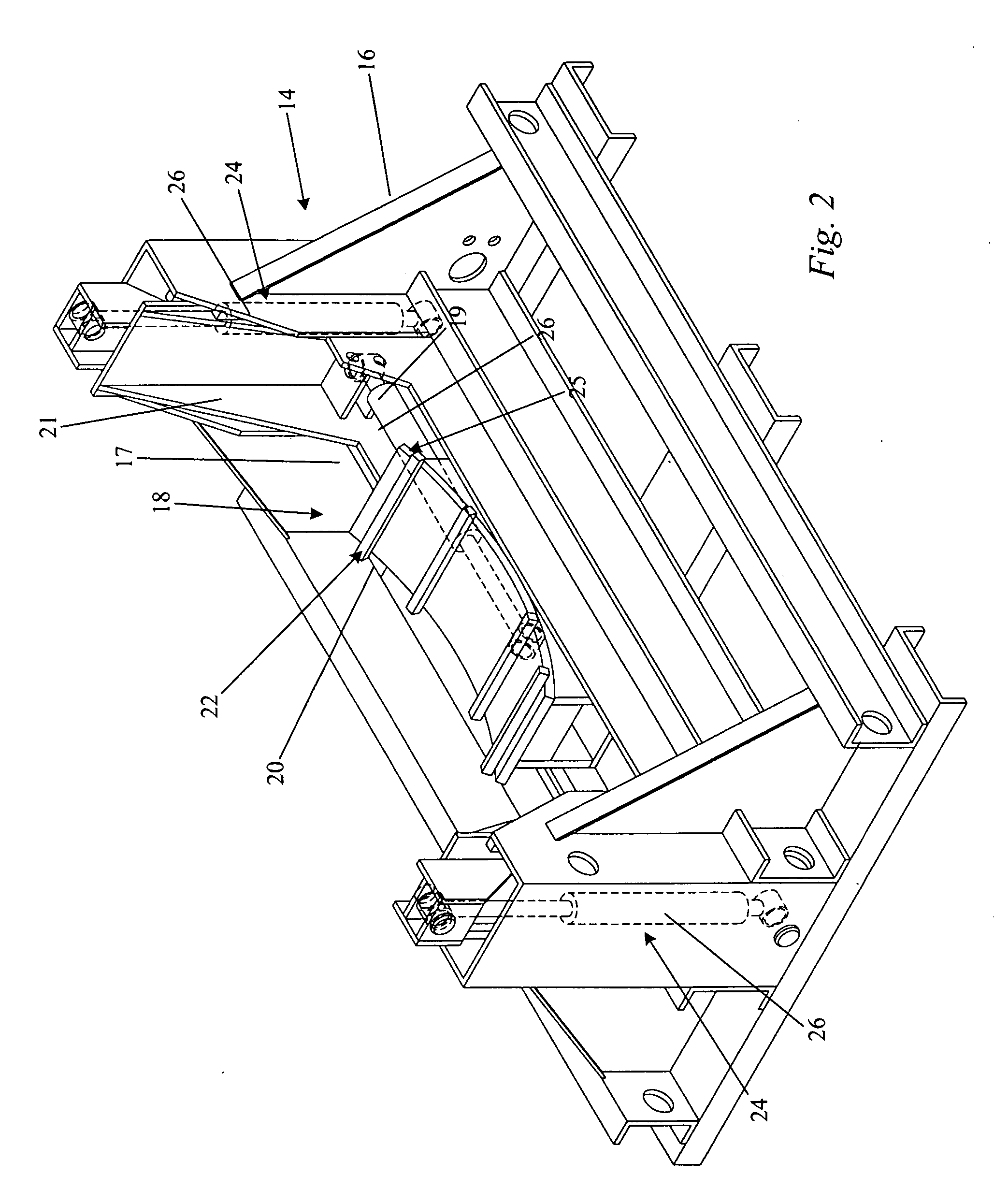
[0014]Referring to FIG. 1, the present invention provides an apparatus or skid 10 that supports and positions large ductile pipes or pipe sections 12 (such as iron or steel pipe that may range from 12 inches to 160 inches in diameter and be any range of lengths, from 5′ to 180′.) during a pipe ramming operation during which a ramming tool 13 such as a pneumatic impact rammer engages the pipe 12 at its rear end and is operated to push the pipe 12 progressively into the ground. This compares with the known method wherein pipe sections lying on the ground of an earthen entry ramp are supported by H-beams or boards and the like at front and rear. According to the invention, before moving the first pipe section into place for ramming, a series of skids 14 are placed in the entry zone in spaced positions preferably along a line perpendicular to the entry surface, generally a vertical dirt wall, such as along the side of a railroad track bed, highway, canal, or under a building, as shown i...


PUM


Abstract

A method of driving a pipe into the ground includes steps of placing a pipe to be driven into the ground onto a series of at least two spaced skids each having an upwardly opening cradle thereon so that the pipe spans and is supported by the skid cradles, one skid proximate a front end of the pipe and the other skid proximate a rear end of the pipe, each skid including a vertical jack mechanism for raising and lowering the pipe supported by the skid, positioning the pipe in a position for ramming into the ground by operating the vertical jack mechanisms as needed to raise the pipe into the ramming position, and ramming the pipe using an impact ramming tool applied to push the pipe into the ground.

Description

[0001]This application claims priority of U.S. provisional application No. 61 / 204,601 filed Jan. 8, 2009.TECHNICAL FIELD[0002]The invention relates to an apparatus and method for positioning an underground pipe for a pipe ramming operation.BACKGROUND OF THE INVENTION[0003]Pipe ramming is a widely used method for installing underground metal pipes especially in large sizes such as 2+ feet in diameter. In one such process, a pneumatic impact tool engages one end opening of the pipeline and forces it through the ground either horizontally or on a vertical grade that departs from horizontal. Wentworth U.S. Pat. No. 5,505,270, Apr. 9, 1996, exemplifies a pneumatic impact tool preferred for use in pipe ramming of large diameter iron and steel pipes and is incorporated by reference herein. Pipe lengths of up to 40 feet are rammed into the ground after which a further pipe section is welded to the exposed end of the installed pipe, and the ramming tool is then relocated to the exposed end o...

Claims


Application Information

Patent Timeline
Patent Type & Authority Applications(United States)
IPC IPC(8): E03F3/06F16L3/01
CPCE21D9/005F16L1/06F16L3/01F16M11/043
Inventor COLEMAN, MICHAEL J.
Owner MPC BEDROCK MONTANA
Features
  • R&D
  • Intellectual Property
  • Life Sciences
  • Materials
  • Tech Scout
  • Unparalleled Data Quality
  • Higher Quality Content
  • 60% Fewer Hallucinations
Learn More