Wide Angulation Coupling Members For Bone Fixation System

a wide angle, bone fixation technology, applied in the field of low profile and wide angle coupling assembly, can solve the problems of reducing the holding strength of the yoke and increasing the potential for failure of the yoke in securely holding the anchor member, and achieve the effect of preserving strength and structural integrity

Active Publication Date: 2010-08-12
PIONEER SURGICAL TECH INC
View PDF103 Cites 235 Cited by
  • Summary
  • Abstract
  • Description
  • Claims
  • Application Information

AI Technical Summary

Benefits of technology

[0003]In one form, a coupling or yoke device is provided with an opening in the coupling device that is sufficiently large to allow an anchor member, such as a pedicle screw or hook, to pivot to relatively extreme angles in a limited number of directions relative to a bottom portion of the coupling device, such as 45-60° or more away from a central axis of the coupling device. In order to provide a coupling assembly that allows the anchor member to pivot to extreme angles in multiple directions relative to a yoke device of the coupling assembly while still preserving the strength and structural integrity of the coupling assembly, the yoke may include a portion that swivels like a turret with respect to another portion. For instance, in one aspect of the invention a first or upper portion of the yoke device retains an elongate member, such as a spinal rod, that is used to connect multiple yokes for fixation of adjacent vertebrae. A second or lower portion of the yoke device may be configured to pivotably receive the anchor member, allowing the anchor member to pivot in a limited number of directions or planes with respect to the lower yoke portion. The second portion of the yoke device that holds the anchor member may be configured like a turret to rotate relative to the first portion while the orientation of the anchor member is varied with respect to the lower member. By configuring the first and second portions of the yoke device so that they are rotatable relative to one another, the anchor member may be pivoted to any desired direction and angle with respect to the elongate member without the necessity of providing significant clearance 360 degrees around the point at which the anchor member exits the yoke device.

Problems solved by technology

However, an increase in the angle and / or size of the opening in a yoke housing reduces the holding strength of the yoke, since increasing the size of the opening requires removal of material from the housing that would otherwise surround the head portion of the anchor member.
Thus, accidental separation of the yoke and anchor member is more likely, increasing the potential for failure of the yoke in securely holding the anchor member therein.

Method used


Image

  • Wide Angulation Coupling Members For Bone Fixation System
  • Wide Angulation Coupling Members For Bone Fixation System
  • Wide Angulation Coupling Members For Bone Fixation System

Examples


Embodiment Construction

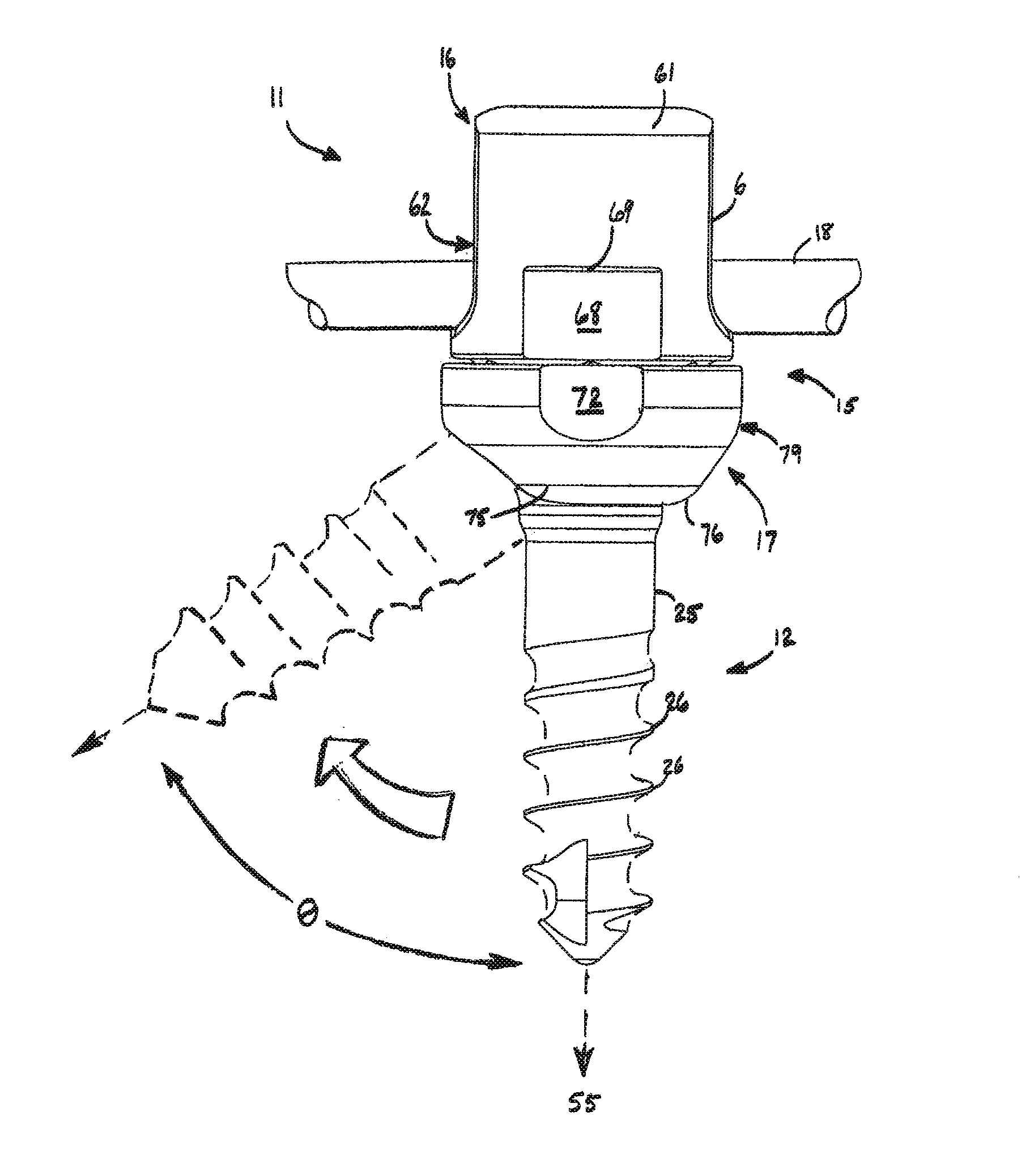
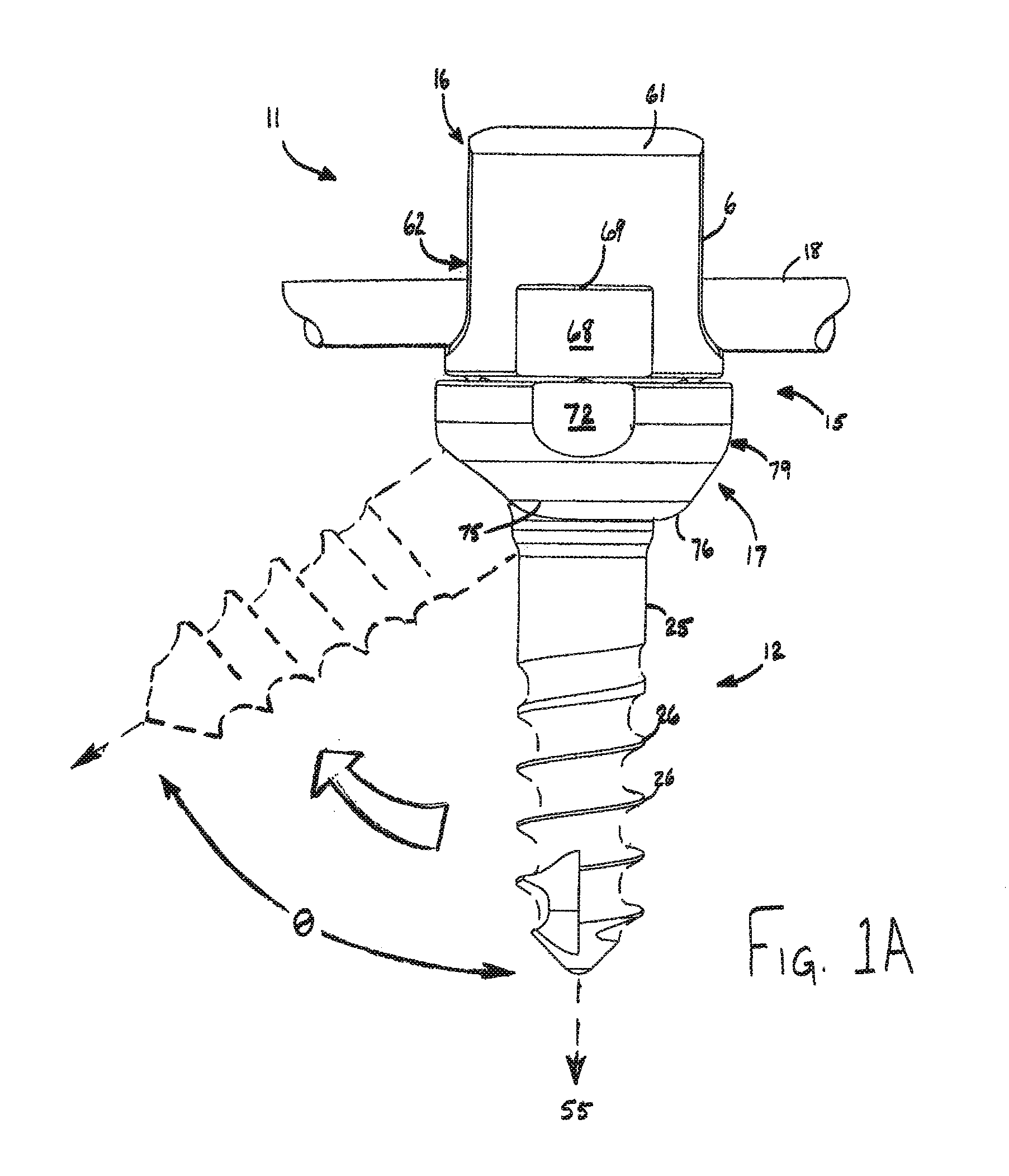
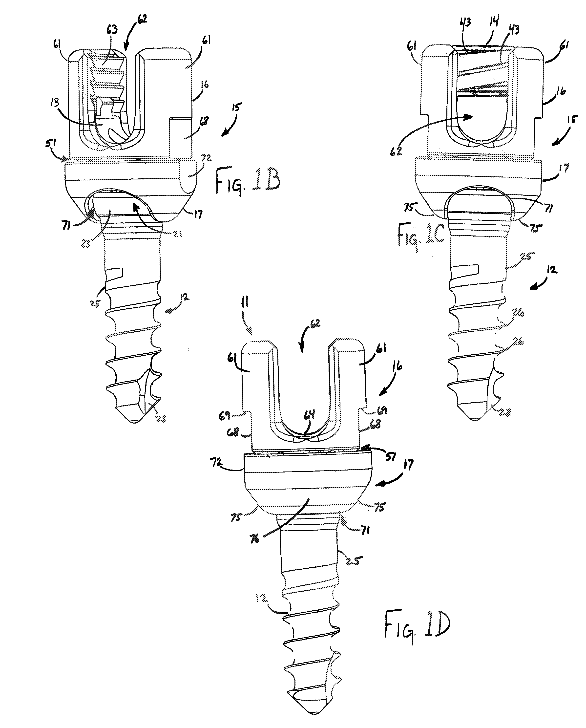
[0034]In one aspect of the invention, a coupling assembly is provided with a two-part yoke device that allows the relative orientation between an anchor member and an elongate member to be widely varied. In prior systems, an anchor is often provided with a spherical or semi-spherical head that may pivot to various angles with respect to the coupling member in which it is retained. For instance, U.S. Pat. No. 7,141,051 illustrates in FIG. 3 thereof a coupling member that receives the head of a pedicle screw and allows the pedicle screw to pivot a relatively small amount away from the axis of a coupling member. This allows the pedicle screw to be fixed at an angle with respect to the central axis of the coupling member, instead of merely allowing the anchor to extend along the central axis. The ability of the anchor to pivot depends greatly upon the configuration of the coupling member or yoke, in that the opening in the yoke must be large enough to avoid interference with pivoting of...


PUM


Abstract

A coupling assembly is provided with a yoke device that allows an anchor member secured thereto to rotate in a turret-like manner with respect to an elongate member secured by the yoke in addition to allowing the anchor member to pivot away from the central axis of the yoke. A first yoke member holds the elongate member and is rotatably coupled to a second yoke member that holds a bone anchor. A combination of rotation of the second yoke member and pivoting of the anchor member allows the anchor to be positioned in a wide variety of orientations with respect to the yoke device and elongate member.

Description

FIELD OF THE INVENTION[0001]The present systems and methods relate to bone fixation devices. More particularly, the present systems and methods provide for a low profile and wide angulation coupling assembly configured to facilitate the internal fixation of vertebral bodies.BACKGROUND OF THE INVENTION[0002]Normally, multi-directional and multi-axial bone anchor systems include an outwardly flared opening at the base of a coupling or yoke member through which an anchor member extends. For instance, in U.S. Pat. No. 7,141,051, a spherical or semi-spherical head at one end of the anchor member is trapped within the yoke housing, and a threaded shank portion of the anchor extends out from the bottom of the yoke housing through an outwardly flared opening. The angle of the outwardly directed flare of the opening in the yoke housing is normally configured to allow the screw shank to pivot to a desired angle in any direction around the axis of the yoke. When the patient's anatomy requires ...

Claims


Application Information

Patent Timeline
Patent Type & Authority Applications(United States)
IPC IPC(8): A61B17/70A61B17/86A61B17/88A61B17/56
CPCA61B17/7037A61B17/7082A61B17/7038
Inventor GEPHART, MATTHEW P.KNAPP, TROY D.
Owner PIONEER SURGICAL TECH INC
Why Eureka
Try Eureka