Imaging device and imaging method

Active Publication Date: 2010-08-19
RICOH KK
View PDF13 Cites 74 Cited by
  • Summary
  • Abstract
  • Description
  • Claims
  • Application Information

AI Technical Summary

Benefits of technology

[0023]According to still another aspect, a computer readable storage medium in which a program is stored is provided. The program allows a computer having an image processing function to execute classifying of a captured image into a plurality of areas according to bri

Problems solved by technology

However, a problem may arise in this technique when a captured image is illuminated with different kinds of light sources that a proper white balance correction on the entire image is not feasible so that a generated image may include color shifts.
To the contrary, images resulted from dif

Method used


Image

  • Imaging device and imaging method
  • Imaging device and imaging method
  • Imaging device and imaging method

Examples


Example

First Embodiment

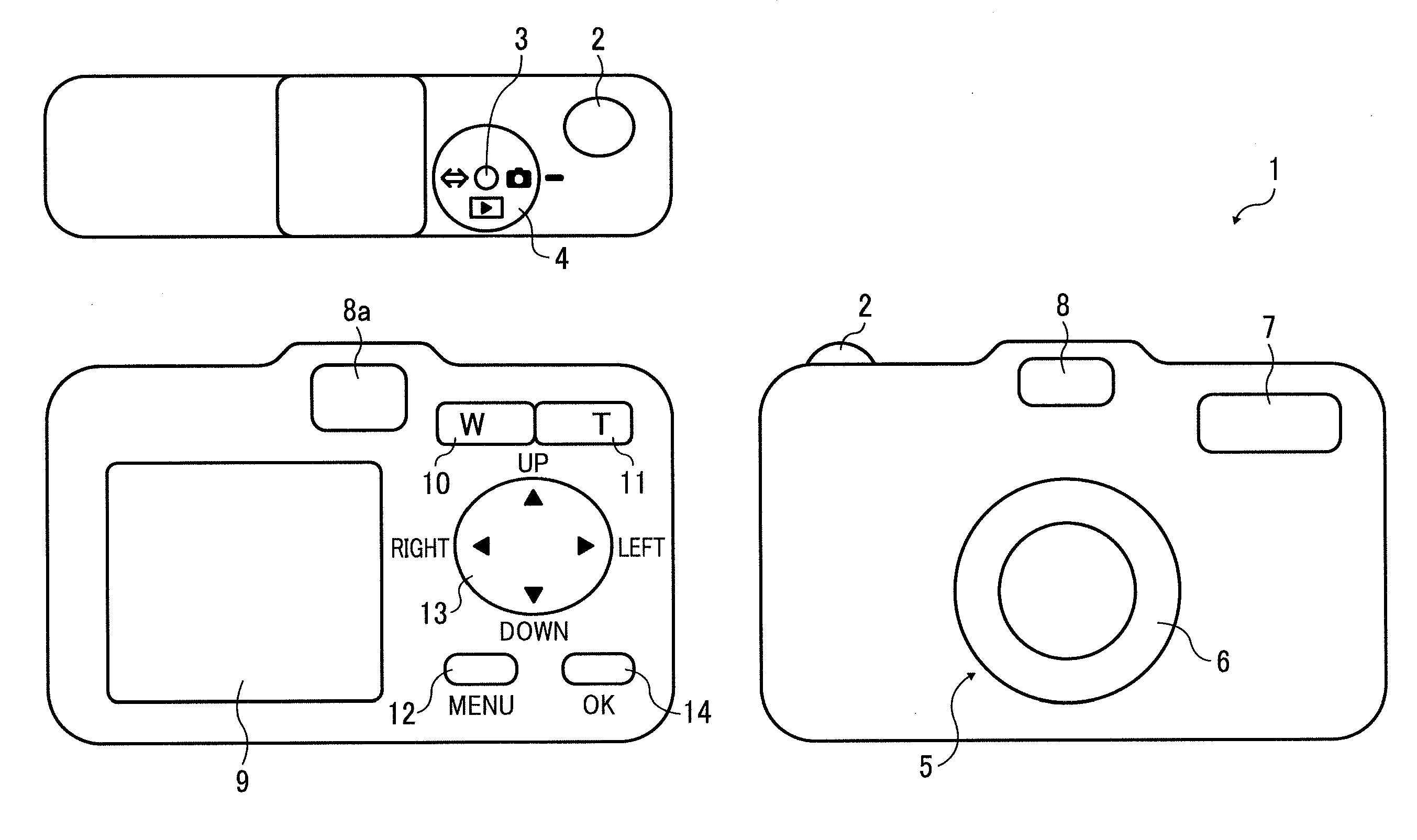
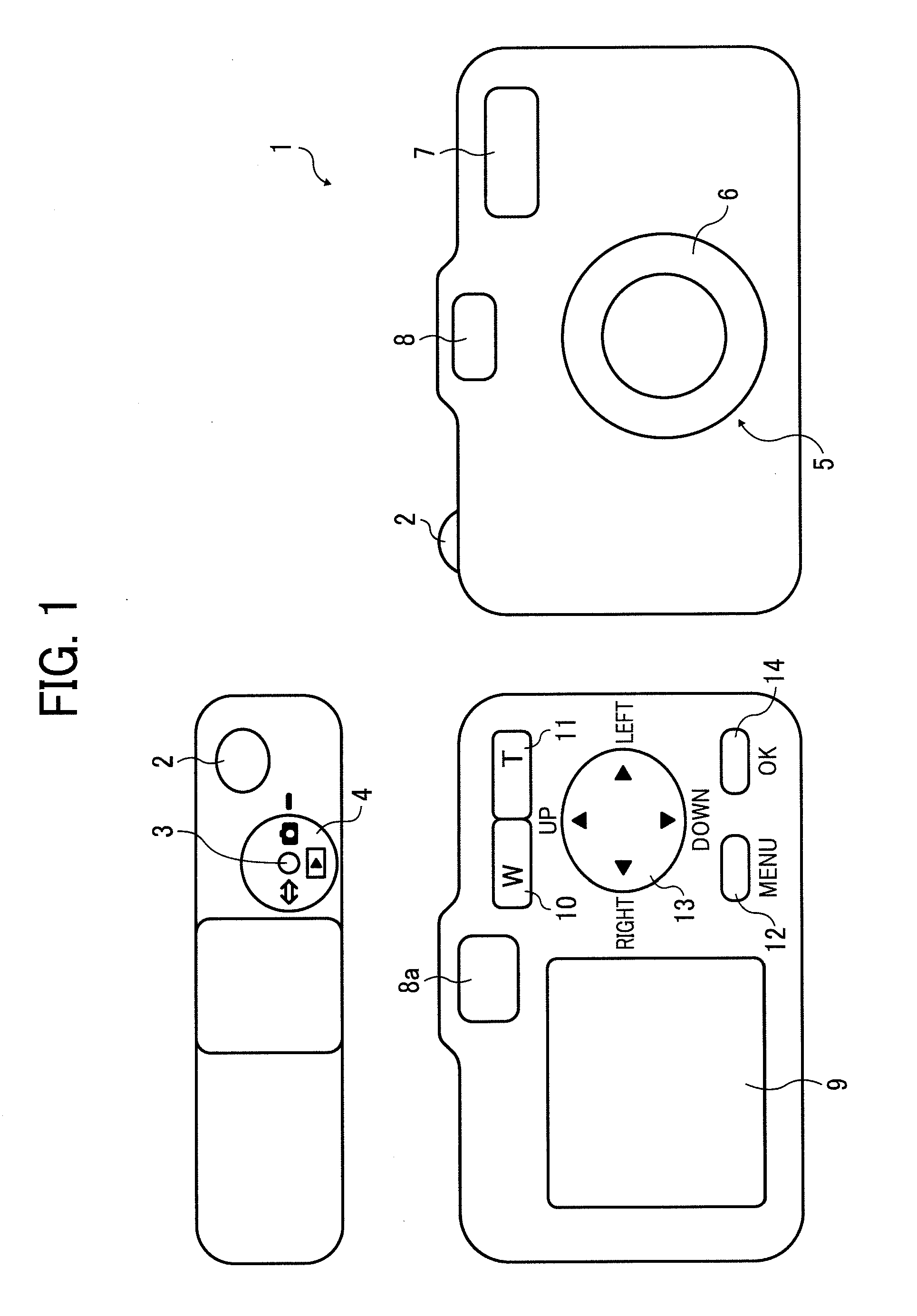
[0048]FIG. 1 schematically shows the exterior of a digital camera as an imaging device of a first embodiment of the present invention. In FIG. 1 a digital camera 1 comprises a shutter button 2, a power-on button 3, and a shooting / reproduction switch dial 4 on a top face as well as a lens barrel 6 having a lens system 5, a strobe light emitting portion 7, and a viewfinder 8 on a front face.

[0049]The digital camera 1 comprises an LCD monitor 9, an eyepiece 8a of the viewfinder 8, a wide-angle zoom switch 10, a telephoto zoom switch 11, a menu button 12, a scene switch button 13, an OK button 14 and the like on a back face. It further comprises, on a side face, a memory card container into which a memory card 15 storing captured image data is inserted.

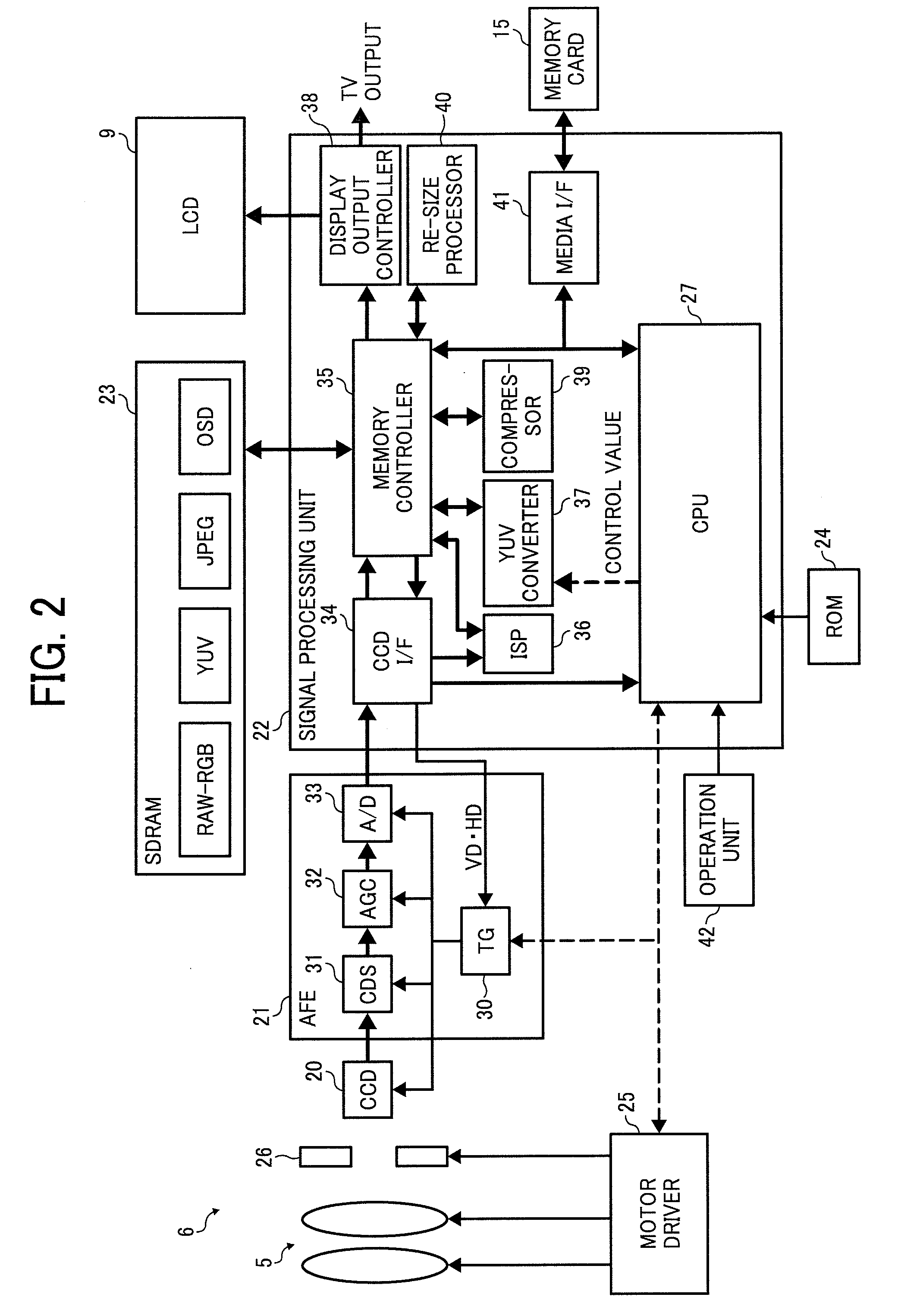
[0050]FIG. 2 shows a structure of the digital camera 1. The digital camera 1 therein contains a CCD 20 as a solid image sensor which forms, on its receiving face, a subject image having passed through the lens system 5 of ...

Example

Second Embodiment

[0121]Now, WB correction of the imaging device according to a second embodiment of the present invention will be described in detail with reference to a flowchart in FIG. 19.

[0122]First, in step S1A, RAW-RGB data are stored in the CCD I / F 34 and a RGB integration value for each of the 256 equally divided blocks 100 is acquired. Note that the number of divided blocks can be arbitrary and the shape of the blocks and the ratio of the blocks to the entire image can be set arbitrarily.

[0123]In step S2A, brightness is calculated from the RGB integration value and the divided blocks 100 are classified into the sunny area and the shadow area based on the brightness and color information, as in step S4 of the first embodiment. In the present embodiment the step 2A is to divide an image into a plurality of areas, the sunny area and the shadow area based on brightness information and color information. The classification of the image into the sunny area and the shadow area is ...

Example

Third Embodiment

[0131]Now, WB correction of the imaging device according to a third embodiment of the present invention will be described in detail with reference to a flowchart in FIG. 20. Note that steps in the present embodiment are the same as steps S1A to S5A of the second embodiment, therefore, a description thereof will be omitted. A difference between the second and third embodiments is in that a new step S4B-2 is added between S4 and S5. The step S4B-2 is described in detail in the following.

[0132]The step S4B-2 is an operation performed when a person's face is detected in a captured image by a known face detection technique (a description omitted). In a case where a facial area includes the sunny area and the shadow area in step S2B, the WB correction coefficients for the sunny area and / or shadow area in the facial area are adjusted so that differences in the coefficients therebetween are to be within a second predetermined range R2 after the adjustment in step S4B-1.

[0133...


PUM


Abstract

An imaging device is configured to include an optical system which captures an image of a subject, an image sensor which converts the image captured by the optical system into an electric signal, a classifying unit which classifies the captured image into a plurality of areas according to brightness information and color information, a white balance correcting unit which set different white balance correction coefficients for the plurality of areas; and a white balance correction coefficient adjusting unit which adjusts a difference in the white balance correction coefficients for the plurality of areas to be within a first predetermined range.

Description

CROSS REFERENCE TO RELATED APPLICATIONS[0001]The present application is based on and claims priority from Japanese Patent Application No. 2009-32220, filed on Feb. 16, 2009 and No. 2009-60056, filed on Mar. 12, 2009, the disclosure of which is hereby incorporated by reference in its entirety.BACKGROUND OF THE INVENTION[0002]1. Field of the Invention[0003]The present invention relates to an imaging device and an imaging method with a white balance correction as well as to a computer readable storage medium in which a program to allow a computer to execute a white balance correction is stored.[0004]2. Description of the Related Art[0005]There has been a widely used technique in the field of an imaging device to determine a light source of uniform light in an entire captured image and perform the same level of a white balance correction on the entire image. However, a problem may arise in this technique when a captured image is illuminated with different kinds of light sources that a p...

Claims


Application Information

Patent Timeline
IPC IPC(8): H04N9/73
CPCH04N9/735G06K9/00255G06V40/166H04N23/88
Inventor NOMURA, KENICHIROH
Owner RICOH KK
Why Eureka
Try Eureka