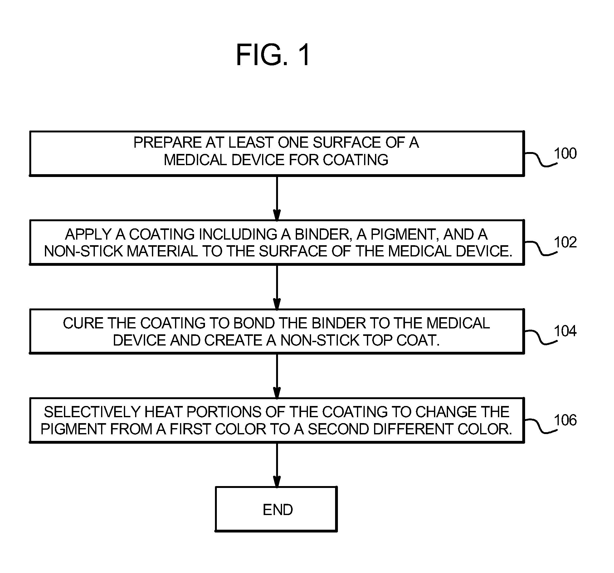
[0012]In one embodiment, a coating is applied to the surface of a
medical device, such as a medical wire. The coating includes a binder, at least one heat-sensitive
pigment, at least one relatively heat-stable
pigment and particles of a low-friction material such as PTFE. The medical device and the applied coating are then heated above a designated temperature, such as 500° F. (260° C.) to cure the coating. The binder and
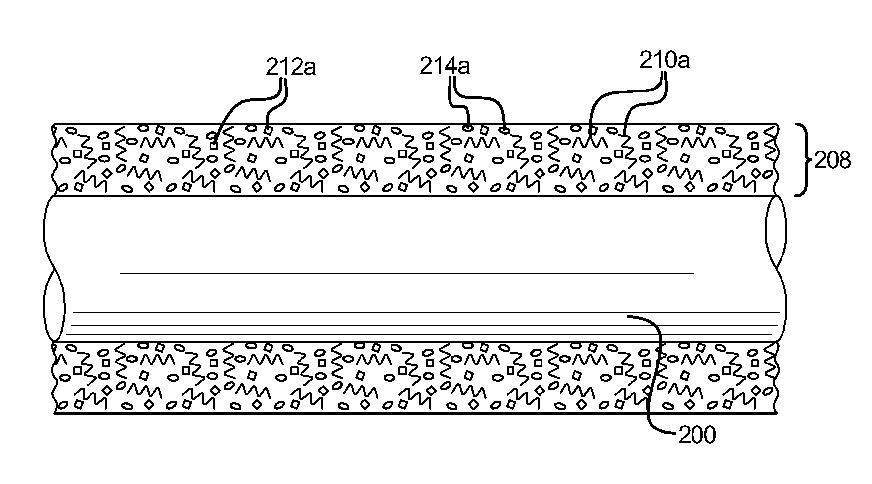
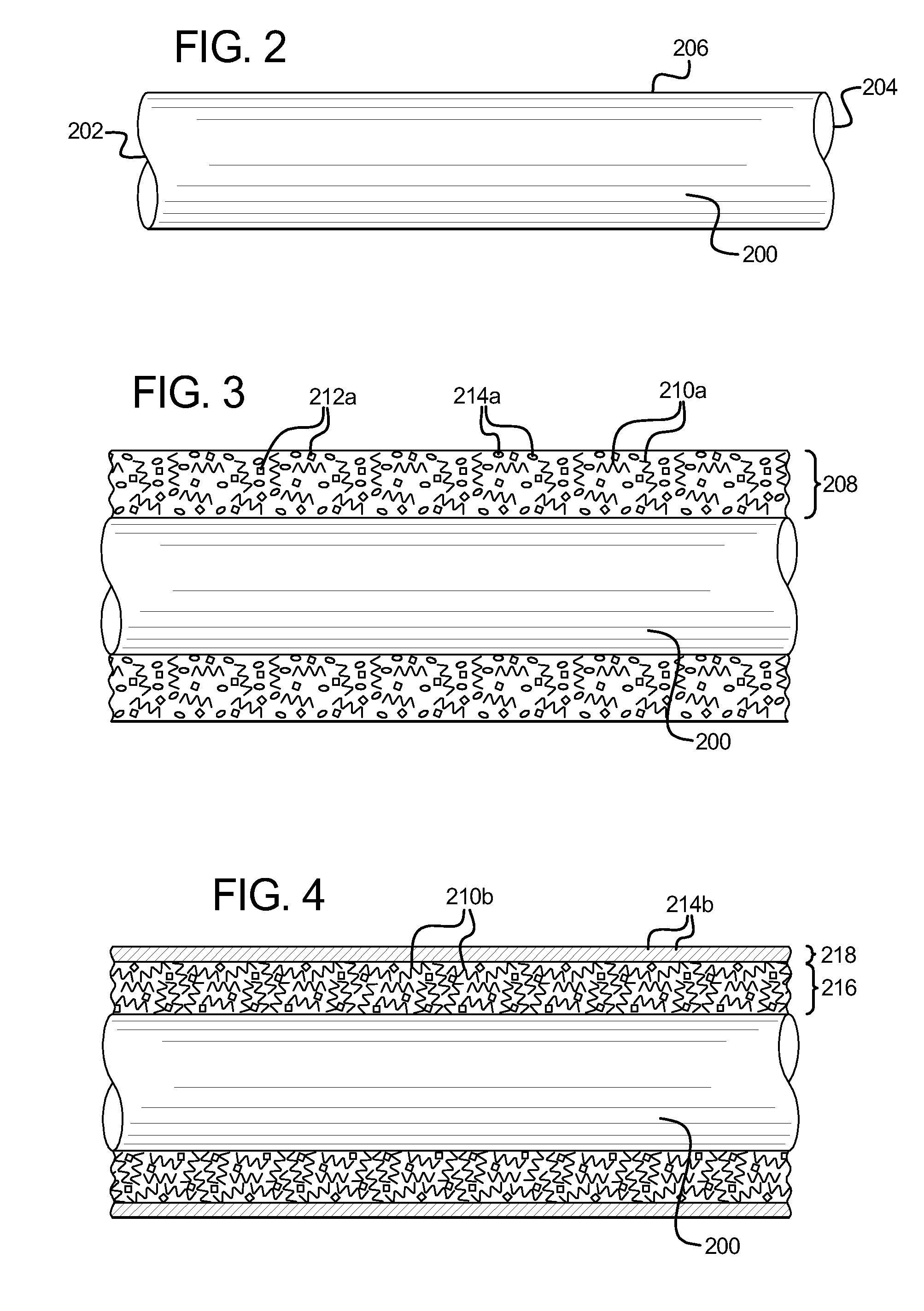
heat sensitive pigment used in this method are generally stable at the cure temperature, but one or both will discolor or shift color at temperatures above a specific temperature greater than 500° F. (260° C.). During the initial curing process, the low-friction particles soften and at least some of the low-friction material migrates or flows to the surface of the coating due to the different rates of curing of the low-friction particles and the binder. At or near the surface of the coating, the low-friction material fuses or glazes over the base layer to create a smooth, substantially continuous top coat comprised of low-friction material. Also during the curing process, the binder material binds with the surface of the medical device and the heat activated pigment is left interspersed within the binder material. When curing is complete, the medical device includes a base layer including a binder material and a heat activated pigment, and an at least partially transparent top coat substantially comprised of
low friction or low
surface energy materials. One
advantage of this method over the
aqueous solution method of applying a coating is that the coating in this method is cured at a lower temperature, which enables the
heat sensitive pigment to be formulated to shift color at a lower temperature. The lower color shifting temperature enables the color of the
heat sensitive pigment (which is under the outer, relatively transparent low-friction coating) to shift without substantially affecting, degrading, deteriorating, compromising or changing the
chemical composition of the low-friction material of the coating and / or affecting, degrading, deteriorating, compromising or changing one or more characteristics, functions, or properties of the low-friction material of the coating. The lower color shifting temperature also enables the color of the pigment to shift without substantially affecting, degrading, deteriorating, compromising or changing one or more characteristics, properties, or functions of the adherence of the coating to the surface of the medical device.
[0013]After initially curing of the specific coating on the surface of the medical device, markings in the coating are created by selectively heating portions of the coating, including the heat activated pigment, above a color shifting temperature, or by selectively stimulating portions of the coating by using a suitable external
stimulant. The color shifting temperature must be greater than the curing temperature, so that the pigment does not shift or
change color during the curing process. The color shifting temperature must also be less than the temperatures at which either the binder material significantly loses its adhesion to the surface of the medical device, or the low-friction material of the coating substantially degrades. That is, if the color shifting temperature is too high, then the low-friction character of the top coat will degrade (nullifying the effectiveness of the low-friction coating), and the binder material will lose adhesion to the surface of the medical device (causing the coating to deteriorate, delaminate or peel off) before the pigment can be heated above the color shifting temperature. A proper color shifting temperature enables areas of different or contrasting color to be created after curing and without adversely affecting the low-friction character of the top coat or the adhesion of the base layer to the surface of the medical device. Therefore, a proper color shifting temperature enables contrasting color markings to be created on the medical device without adversely affecting the function of the medical device or the coating thereon.
[0014]In one embodiment, a first area of the low-friction coating is heated to the color shifting temperature to shift or change the color of the heat activated pigment for a specific distance, such as 3 mm as measured from the distal end, proximal end or from the center of the medical device. In this embodiment, a distance, such as 10 mm, is then measured from the first area to a second area. The second area, such as an area of 3 mm in length, is subsequently heated to the color shifting temperature to shift or change the color of the heat activated pigment. Such heatings to create areas of shifted color, when repeated in any sequence along the length of the device, result in specific length markings at measured intervals. The markings of such width, depth or distance marked medical devices enable surgeons or other medical professionals to determine, based on a predetermined pattern known to the device user, the length of the medical device inserted into a patient, whether from the proximal or distal end. Accordingly, the medical device and method disclosed herein provide the advantages of having specific markings that do not significantly increase or decrease the
diameter of the medical device, or significantly adversely affect the function of the low-friction coating and further provide a coating over the base material of the medical wire or device.
[0028]After applying the second low-friction layer to the desired portion of the twisted medical device, and
drying or semi-curing the second applied layer so the second coat is sufficiently dry and physically stable, the first end and the second end of the medical device is untwisted or released (to enable the twisted medical device to unwind to a relaxed or
normal state). The coated medical device is then suitably final cured so that both of the low-friction coatings are bonded to each other and bonded to the surface of the medical device. The resulting medical device includes a spiral shaped pattern (around the circumference of the medical device) that extends along part or all of the length of the medical device. That is, the linear strip or band of the second low-friction coating that was applied when the medical device was twisted becomes a spiral shaped strip or band of the second low-friction coating when the same medical device is untwisted and returns to the original configuration. Such a medical device with longitudinal spiral markings enables a medical professional to determine if the inserted medical device is rotating or moving as desired as the medical device enters the
entry point of the patient's body. Such a medical device with longitudinal spiral markings further enables a medical professional to determine if their intended imparted motion of the medical device at the
entry point of the patient resulted in causing the medical device to advance, retract, rotate, be withdrawn or otherwise move in the patient by determining if the spiral markings appear to move. For example, the illusion of movement of the spiral markings of the medical device enable a medical professional to determine if the medical professional's gloved fingers are actually providing the tactile forces to move the medical device as intended and that no unintended slippage of the medical device occurred.
[0029]It is therefore an
advantage of the medical device and method disclosed herein to provide a marked low-friction coated medical device having markings which do not affect the function or form of the low-friction coating and enable a surgeon or other medical professional to determine the length of a medical device inserted into a patient's body, and to modulate the speed at which the medical device is being inserted or extracted from the patient's body. Such coated medical device provides no dynamic restrictions to any predetermined or required modulation of speed due to the removal or interruption of the low-friction coating to the smooth, low-friction outer surface of the device. The medical device and method disclosed herein further provides a marked medical device with a smooth, continuous low-friction surface with a substantially constant
diameter which prevents the medical device from
snagging, sticking, tearing, or otherwise damaging vessels, arteries, or other tissues of a patient during
insertion, positioning, and extraction of the medical device. The low-friction coating is marked without otherwise affecting, degrading, deteriorating, changing the
chemical composition of, changing one or more characteristics, functions, or properties of or removing in the entirety, the low-friction coating. The marked low-friction coated medical device disclosed herein enables a surgeon or other medical professional to smoothly, easily, accurately, and safely insert and position the medical device in a patient's body during a
medical procedure and know what distance is inserted into the patient's body and what distance remains outside of the patient's body. The medical device and method disclosed herein further provides a marked medical device with different slightly elevated bands or areas along the length of the medical device (such as to indicate distance), have low-friction characteristics (including
low friction, low
surface energy and / or non-stick characteristics) and include markings that show up using a suitable imaging device, such as an x-
ray device or on an x-
ray film, to provide an
exact location of the medical device inside a patient for safety and / or measurement purposes.

