Light guide blade with color balancing structures and blue absorption compensation for large screen LED backlight unit

a technology of led backlighting and color balancing structure, which is applied in the direction of planar/plate-like light guides, lighting and heating apparatuses, instruments, etc., can solve the problems that the recent increase of attention and effort of light emitting diodes (leds) and achieves improved light recycling efficiency, high efficiency, and high blue absorption.

Active Publication Date: 2009-12-24
JABIL CIRCUIT INC
View PDF3 Cites 18 Cited by
  • Summary
  • Abstract
  • Description
  • Claims
  • Application Information

AI Technical Summary

Benefits of technology

[0012]One or more embodiments of the present invention use containing surfaces to prevent light leakage around the sides of a light guide, in order to provide higher efficiency.
[0013]One or more embodiments of the present invention may use a dichroic coating at a distal end of the light guide, or a color filter prior to a reflector at the distal end, in order to partially filter red light. The filtered light is re-injected into the distal end, counter-propagating toward a proximal end of the light guide. Filtering red light will help compensate the color shift due to higher blue absorption in the plastic material of the light guide, so that the resulting color distribution is more uniform along the light guide.
[0014]One or more embodiments of the present invention may use a recycling enhancement component, such as a high-reflectivity reflector or a Mylar film, in addition to a back reflector underneath the light guide, in order to improve the light recycling efficiency. Such recycling enhancement approach can increase the brightness on the screen without the increase of light output or power of LEDs.
[0015]One or more embodiments of the present invention provide a light-transmissive light guide for improving color and brightness uniformity of a display backlight. The light guide is made from an elongated light-transmissive bulk material having a proximal end, a distal end, a top major surface, and a bottom major surface opposing the top major surface. The light guide has an input window on the proximal end transverse to the top and bottom major surfaces, configured to allow light from a plurality of light sources to enter the bulk material. The light guide further has a viewing area of the bulk material comprising a portion of the top and bottom major surfaces on which a plurality of micro-lenses are disposed. The light guide further has a color mixing region of the bulk material adjacent to the viewing area comprising at least one light containing surface transverse to the top and bottom major surfaces, the mixing region configured to mix light from the plurality of light sources and communicate the light, after mixing, to the viewing area. The light guide further has a color balancing region of the bulk material disposed between the input window and the mixing region, comprising at least one color balancing surface transverse to the top and bottom major surfaces, the color balancing region configured to balance color light from at least two of the light sources of different colors and communicate the light, after color balancing, to the mixing region, wherein the color balancing surface is separated from the light containing surface by a distance determined by its specific function and feature.
[0016]One or more embodiments of the present invention provides a method for improving color uniformity of a display backlight, the method including steps of coupling light from a plurality of lights sources, through an input window, into an elongated light-transmissive bulk material, balancing the color light from at least two of the plurality of light sources in a color balancing region of the bulk material, following the balancing step, mixing the light in a mixing region of the bulk material, and after the mixing step, emitting the light from the bulk material through a plurality of micro-lenses disposed in a viewing area of the bulk material.
[0017]Advantages of the present invention, compared to devices known in the conventional art, include, first, providing a light guide having a relatively shorter color mixing distance. Second, a more uniform color distribution is provided at a portion of viewing area nearest to the LEDs (i.e., the proximal end of the light guide). Third, higher coupling efficiency can be achieved. Fourth, brightness can be improved by using a light recycling enhancement component on the bottom surface of a backlight unit. Fifth, color shift due to blue absorption by the bulk plastic material of the light guide can be properly compensated. The features of the present invention providing these advantages have been integrated with unique light guide structures, thereby providing a low-cost, high-performance and slim LED backlight unit with progressive scanning illumination features.

Problems solved by technology

The backlighting is conventionally provided by light sources such as CCFL, but light emitting diodes (LEDs) recently have attracted greater attention and effort.

Method used


Image

  • Light guide blade with color balancing structures and blue absorption compensation for large screen LED backlight unit
  • Light guide blade with color balancing structures and blue absorption compensation for large screen LED backlight unit
  • Light guide blade with color balancing structures and blue absorption compensation for large screen LED backlight unit

Examples


first embodiment

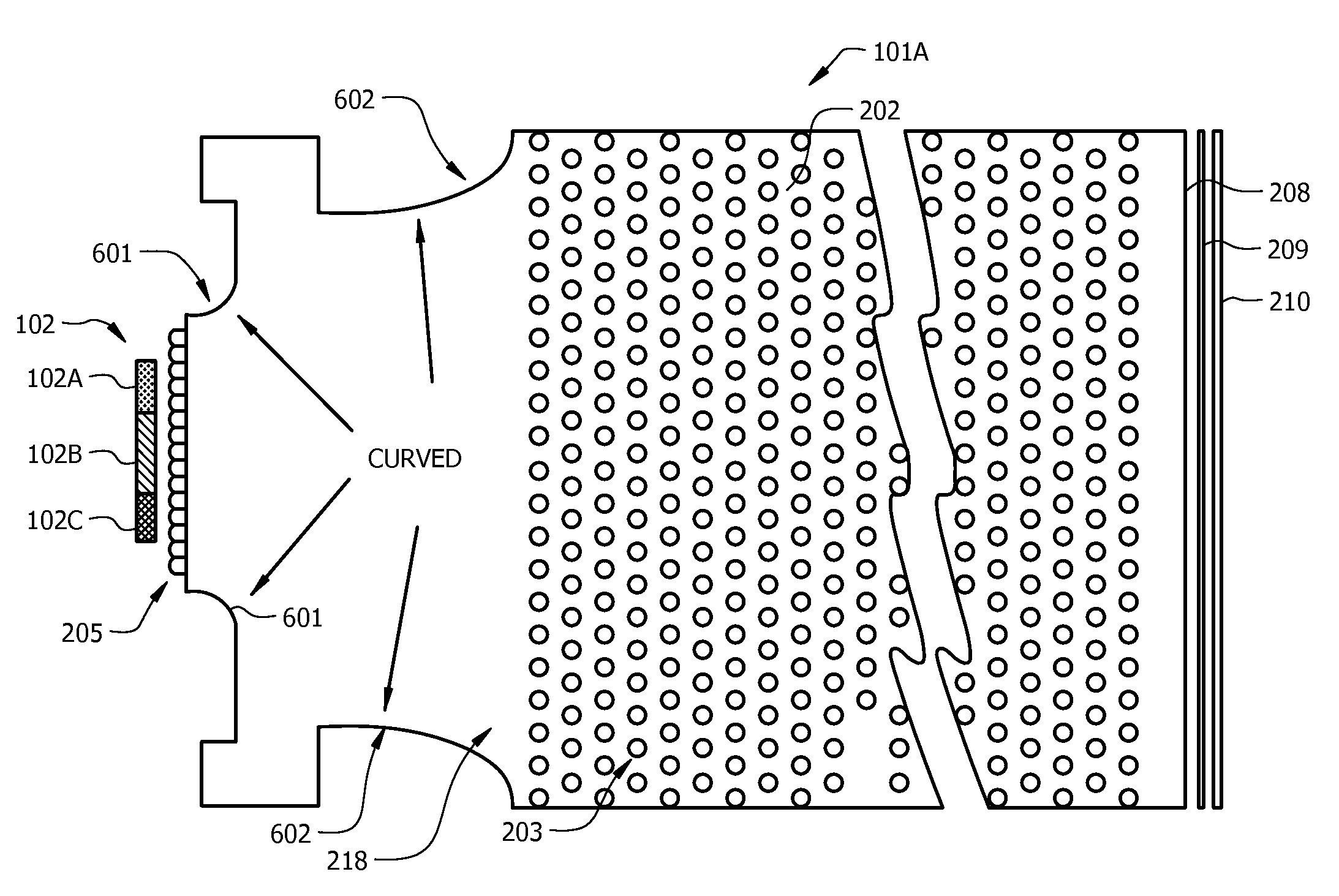
[0071]The wavelength-dependent absorption of the bulk plastic material of light guide 101A typically attenuates the shorter (i.e., blue) wavelengths more so than longer (i.e., red) wavelengths. Uncompensated, this tends to produce a reddish tinge to light emitted around the distal end of the micro-lens array 203. The light emitted from distal end 208 of the light guide will also have a reddish tinge. FIG. 8A illustrates a color compensation scheme. FIG. 8A shows a color filter 209 positioned beyond distal end 208, with reflector 210 positioned beyond color filter 209. Color filter 209 is designed to selectively attenuate longer wavelengths (i.e., red color) compared to shorter wavelengths (i.e., blue). The filtered light is reflected by reflector 210, filtered a second time by color filter 209, and reintroduced into distal end 208 of the light guide 101A, counter-propagating toward the proximal end 218 of light guide 101A. The twice-filtered light will have a blue to cyan tinge, cya...

second embodiment

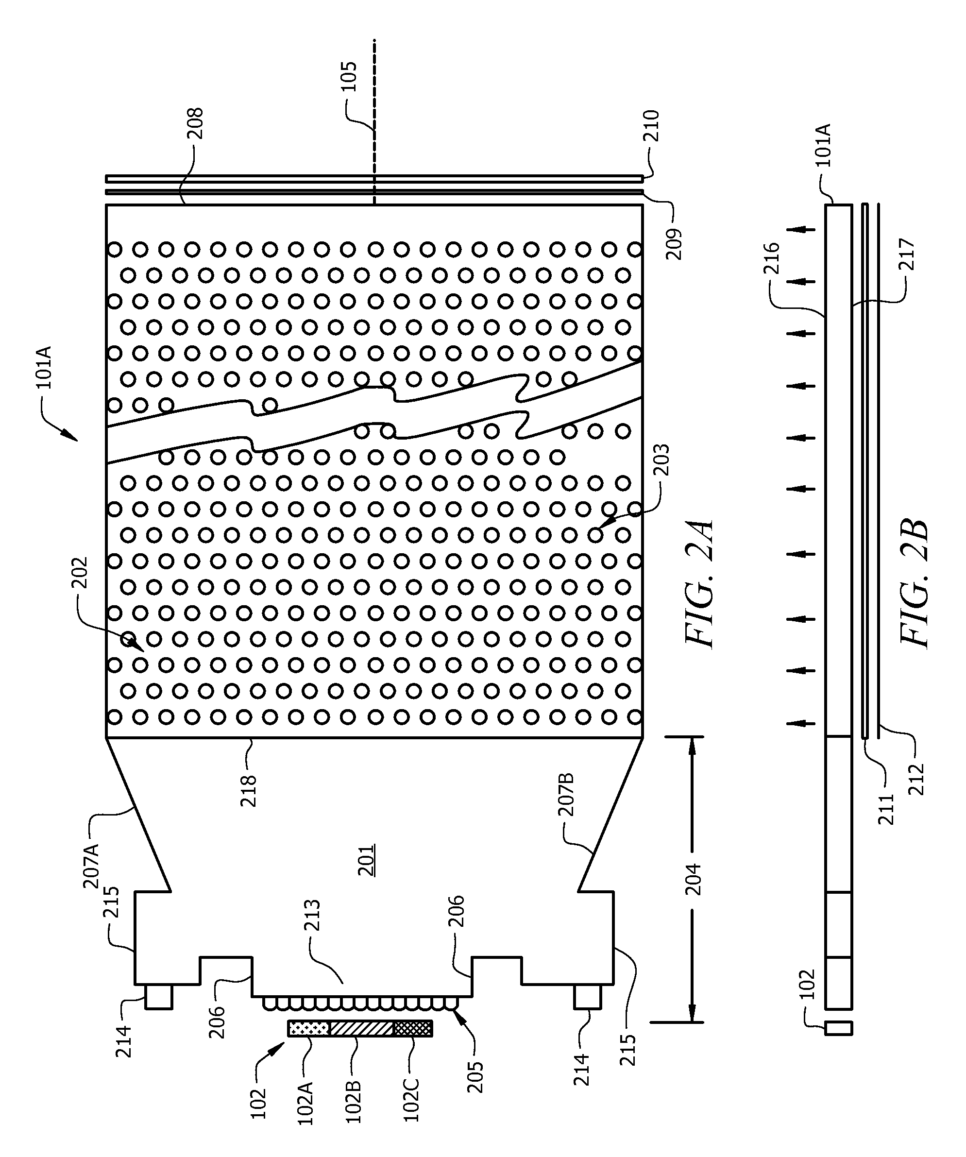
[0072]FIG. 8B illustrates a color compensation scheme. FIG. 8B shows a dichroic mirror 211 positioned beyond distal end 208. Dichroic mirror 211 is designed to selectively reflect shorter wavelengths (i.e., blue) compared to longer wavelengths (i.e., red color). Light not reflected by dichroic mirror 211 passes through dichroic mirror 211 and is damped. The reflected light is reintroduced into distal end 208 of the light guide 101A, counter-propagating toward the proximal end 218 of light guide 101A. The reflected light will have a blue to cyan tinge, cyan being the combination of blue and green light. The reflected, counter-propagating light combines with the reddish-tinged propagating light to produce a compensated light emitted near the distal end of the micro-lens array 203. The compensated light has a more balanced color spectrum so that the color distribution is more uniform across the light guide.

[0073]FIG. 8C qualitatively illustrates the spectrum of light emitted from dista...


PUM

PropertyMeasurementUnit
thicknessaaaaaaaaaa
wavelength rangeaaaaaaaaaa

Abstract

One or more embodiments of the present invention provide apparatuses, methods and systems to form a thin LED backlight unit for a large-screen flat-panel display. The backlight unit is able to achieve improved color mixing within a shorter mixing distance than the conventional art, while maintaining desired brightness uniformity, thereby allowing for a shorter bezel of a display device. One or more embodiments of the present invention include one or more light guides, which, by operating together, provide thin backlight units. High system efficiency is provided by introducing a recycling enhancement component, and uniform color distribution is achieved by incorporating color shift compensation. Multiple light guides are arranged adjacent to one another can offer a progressive scan illumination feature.

Description

CROSS REFERENCE TO RELATED APPLICATIONS [0001]This non-provisional U.S. Patent Application claims the benefit of U.S. Provisional Patent Application No. 61 / 073,558 entitled “LIGHT GUIDE BLADE WITH COLOR BALANCING STRUCTURES AND BLUE ABSORPTION COMPENSATION FOR LARGE SCREEN LED BACKLIGHT UNIT” filed on Jun. 18, 2008.BACKGROUND OF THE INVENTION[0002]1. Statement of the Technical Field[0003]This invention pertains to high-efficiency LED-based backlighting devices used for large screen flat panel LCD displays, in particular for light guide blades having short color mixing distance and uniform distribution of brightness and color in the illumination area.[0004]2. Description of the Related Art[0005]Flat panel LCD displays use backlighting to illuminate the panel for making color images visible. The backlighting is conventionally provided by light sources such as CCFL, but light emitting diodes (LEDs) recently have attracted greater attention and effort. LEDs can be located directly on th...

Claims


Application Information

Patent Timeline
Patent Type & Authority Applications(United States)
IPC IPC(8): G02F1/13357
CPCG02B6/0016G02B6/0018G02B6/0076G02B6/0068G02B6/0036
Inventor LI, LINMOREJON, ISRAEL J.
Owner JABIL CIRCUIT INC
Why Eureka
Try Eureka