

Liquid crystal panel and liquid crystal display
a liquid crystal panel and liquid crystal display technology, applied in the field of liquid crystal panels, can solve the problems of significant change in image color depending on viewing angle, insufficient overcomement of color shift in oblique directions, etc., and achieve the effect of less discoloration of images
- Summary
- Abstract
- Description
- Claims
- Application Information
AI Technical Summary
Benefits of technology
Problems solved by technology
Method used
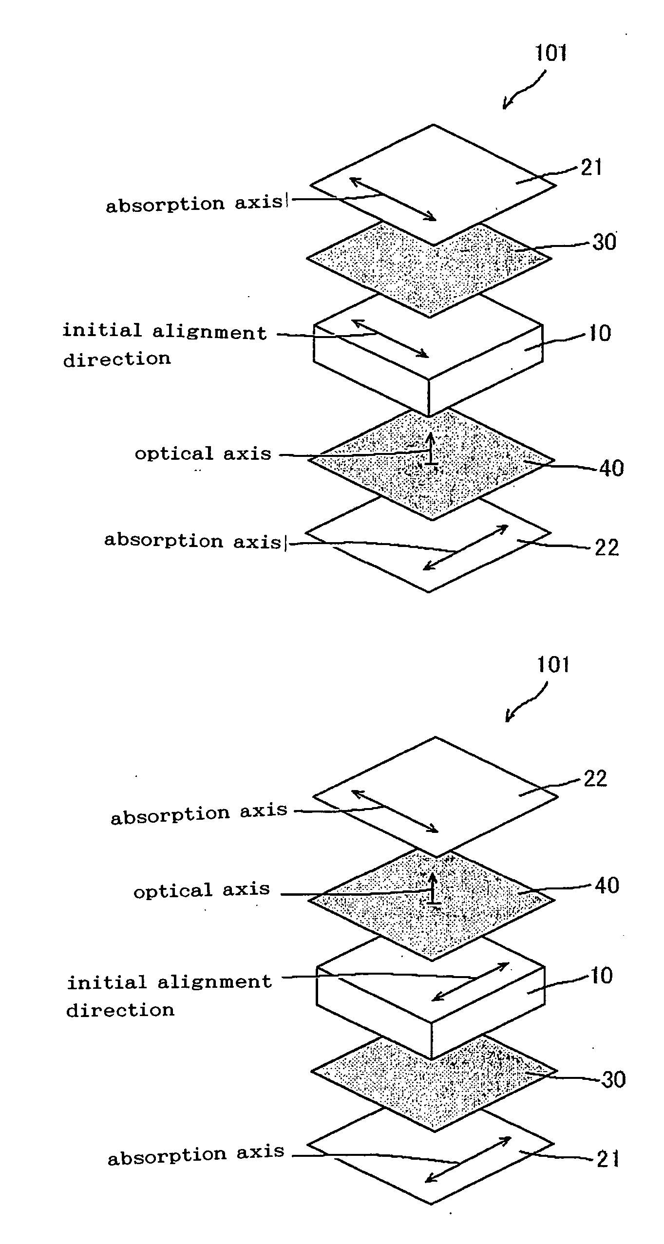
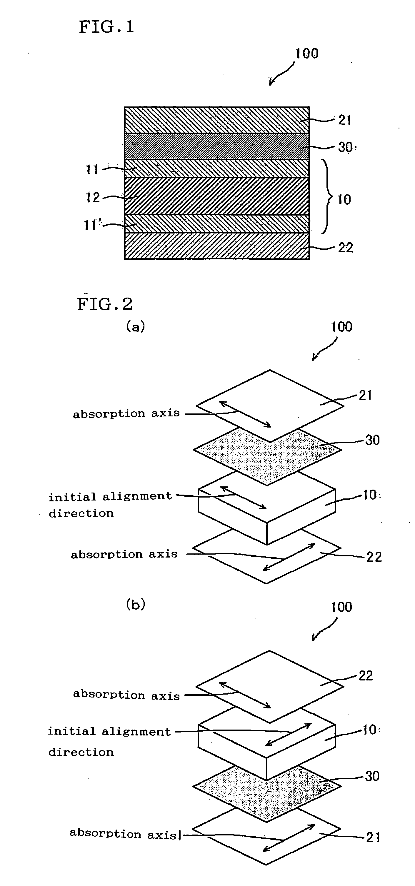
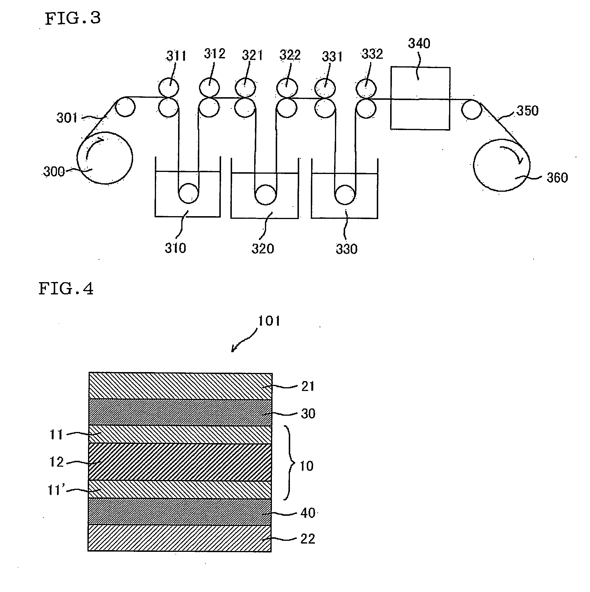
Image

Examples
reference example 1
(Preparation of Polarizers)
[0170] A polymer film mainly composed of polyvinyl alcohol (9P75R (trade name), 75 μm in thickness, 2,400 in average degree of polymerization, 99.9% by mole in saponification degree, manufactured by Kuraray Co., Ltd.) was uniaxially stretched 2.5 times with a roll stretching machine, while being dyed in a dye bath containing iodine and potassium iodide and maintained at 30° C.±3° C. The polyvinyl alcohol film was then uniaxially stretched so as to have a length 6 times the original length, while being subjected to a crosslinking reaction in an aqueous solution containing boron and potassium iodide and maintained at 60° C.±3° C. The resulting film was dried for 30 minutes in an air circulation type thermostatic oven at 50° C.±1° C., so that polarizers (named P1 and P2) were obtained. The optical properties of Polarizers P1 and P2 are as shown in Table 1.
TABLE 1Reference Example 1PolarizerP1, P2Moisture Percentage (%)26Thickness (μm)28Single-Piece Transm...
reference example 2
(Preparation of First Optical Element)
[0171] A 40 μm-thick norbornene resin-containing polymer film (ZEONOR ZF14-040, 1.53 in average refractive index, manufactured by OPTES INC.) was used without being processed and named Polymer Film 1-A, whose properties are as shown in Table 2.
reference example 3
[0172] An 80 μm-thick cellulose resin-containing polymer film (ZRF 80S (trade name), 1.48 in average refractive index, manufactured by Fuji Photo Film Co., Ltd.) was used without being processes and named Polymer Film 1-B, whose properties are as shown in Table 2.
PUM
| Property | Measurement | Unit |
|---|---|---|
| thickness direction retardation | aaaaa | aaaaa |
| thickness | aaaaa | aaaaa |
| thickness | aaaaa | aaaaa |
Abstract
Description
Claims
Application Information