METHOD FOR SECURING MEDICAL DEVICES TO TREAT OBESITY, GASTRO-ESOPHAGEAL REFLUX DISEASE (GERD) AND IRRITABLE BOWEL SYNDROME (iBS) REVERSIBLY

a technology of medical devices and staples, applied in the field of medicine, can solve the problems of insufficient in certain cases, inability to reversibly secure conventional stapling with rigid staplers, and inability to stapling with rigid staplers, and achieve the effect of facilitating the passage of threads

Inactive Publication Date: 2010-09-16
GODIN NORMAN
View PDF9 Cites 25 Cited by
  • Summary
  • Abstract
  • Description
  • Claims
  • Application Information

AI Technical Summary

Benefits of technology

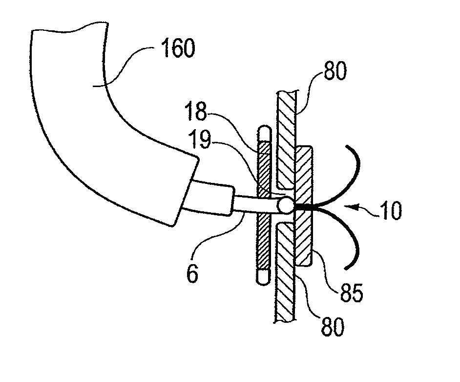
[0025]Another aspect of the invention is a surgical method comprising attaching a medical device to the inner mucosa of a gastro-intestinal tract of a patient with a the gull shaped staple using a conventional straight viewing video or fiberoptic endoscope or a lateral viewing endoscope for positioning of the staples. In order to assure stability and avoid a back jump of the flexible endoscope while firing, an inflatable balloon can be attached at the tip of the endoscope and inflated before firing the staple. The balloon is deflated after firing so that the forceps can move and release or ungrasp the staple. Alternatively, an overtube with an internal part sold by US Endoscopy under the name the Guardus overtube can also be used with or without the internal introducer part to give stiffness to the endoscope when firing the staple.
[0029]Another aspect of the invention, a device as described in my U.S. Pat. No. 6,764,518, referred to as the GARD device, can be inserted through the mouth and the esophagus and, when located at the intersection of the esophagus and stomach mucosa, a ring portion of the GARD device is stapled to a hiatus hernia with the gull shaped staples using a flexible endoscope with forward view or lateral view as in a standard gastroscope or a lateral view duodenoscope, which facilitates precise placement and stapling. In some embodiments the ring described in my aforementioned U.S. Pat. No. 6,764,518, FIG. 1, is modified. Oval holes are punched through the ring at regular intervals around the circumference. In certain embodiments, the spring in the ring has 10 loops and, under every second loop, an oval hole is punched through the ring. The oval hole has to be wide enough to fit the tip of the flexible catheter holding the staple. Around the ring, a narrow 0.2 mm to 0.3 mm net or mesh of polypropylene or a net made of another biocompatible material dipped in silicone is glued around the ring to close the holes. This configuration allows the tip of the catheter with the staple to fit into the niche created by the holes to avoid slippage of the catheter before shooting the staple. Also, the thinner wall created by the net will allow the staple to hold the ring and attach the ring and the device to the wall of the esophagus / hernia. In order to make the oval holes more visible endosopically, a colored marking such as a black ring of biocompatible silicone around the hole can be added to make the niche more visible for the endoscopist and help him / her see the holes for stapling.
[0030]In certain embodiments, a balloon is attached outside of the endoscope. Before shooting the staple with the catheter, the balloon is inflated. The inflated balloon blocks the tip of the endoscope in the ring of the GARD device or the ring of the OB tubes and prevents the endoscope from jumping back or backfiring when the staple is fired. The inflation of the balloon allows better penetration of the staples through the ring and into the tissues without risking a back movement of the flexible endoscope and incomplete penetration of the staple, which can happen when no balloon is used. After the staple is fired, the balloon is deflated. The selection of the diameter of the inflated balloon depends on the diameter of the endoscope and the inner size of the ring. The diameter of the inflated balloon in some embodiments is between 5 mm and 25 mm, preferably between 10 mm and 20 mm. The purpose of the balloon is to make the tip of the flexible endoscope more rigid. Alternatively the inner tube of a Guardus overtube can be used. The inner tube acts like a rigidifying sheath for the flexible endoscope and allows better penetration of the staples through the silicone ring, closing the holes and the tissues to which the device has to be attached.
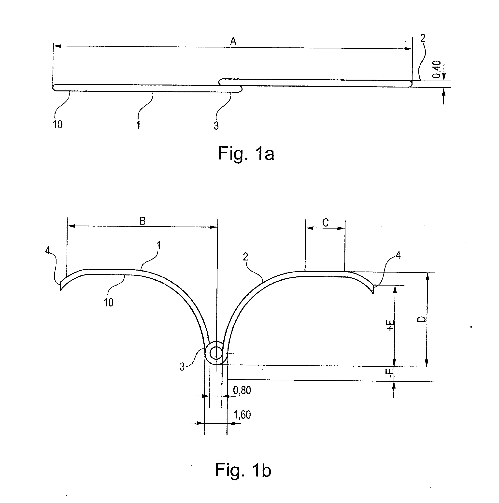
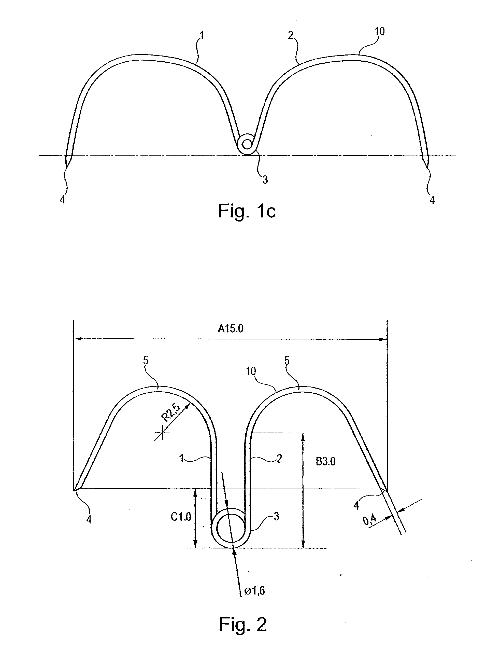
[0034]The staple is preferably constructed of nickel-titanium alloy, and staples of such material are novel and advantageous for several reasons. In most embodiments the staple will use the hyperelastic characteristic of nickel-titanium alloy, allowing folding under stress in a narrow tube for placement in a catheter and resuming the original position when unstressed without permanent deformation of the staple.
[0036]For permanent applications such as with a GARD device, the flexible joining material can be made in implant grade steel, nitinol, surgical thread, or implant grade polymer such as nylon, for example. However, nitinol (nickel-titanium alloy) is the preferred material because of its hyperelastic characteristics. The wing at each end of the joining member can also be made of steel, nitinol, implant-grade polymers such as nylon or any other biocompatible implantable material. In a preferred embodiment, the wing and flexible joining segment are each made of a non-absorbable material, preferably the aforementioned nitinol alloy which exhibits the flexibility needed when released from the catherer. In most cases the staples are constructed in an hyperelastic nickel-titanium alloy that does not use the configuration changes from martensite to austenite. The hyperelastic characteristics of the nickel-titanium alloy allows the staples to be pulled (loaded) in a relatively narrow catheter of 2 mm to 3.0 mm in diameter and when released to conserve the hyperelastic characteristics and almost instantly resume the original wing shaped configuration to function as a staple. To remove the staple, in one embodiment a toothed forceps grasps the loop of the staple and the staple is pulled back into the catheter for removal through the endoscope. An important advantage of certain embodiment of the invention is the reversibility of the stapling operation and the simplicity of the removal of the staples.
[0041]In some embodiments a tilt-tag is attached to the central loop with a non-resorbable surgical thread to prevent the staple from being placed too deeply and to help in retrieving the staple.

Problems solved by technology

Furthermore, the stapling system of this patent is not reversible.
For certain types of devices placed through the mouth, conventional stapling with a rigid stapler is not possible and so various alternatives using flexible instruments have been devised.
While the aforementioned method of placing a GARD worked for some patients, it was insufficient in certain cases.
Furthermore, the Fritscher-Ravens, et al., system was not described for use for securing medical devices, for example a GARD, to the gastrointestinal tract or any other organ.

Method used


Image

  • METHOD FOR SECURING MEDICAL DEVICES TO TREAT OBESITY, GASTRO-ESOPHAGEAL REFLUX DISEASE (GERD) AND IRRITABLE BOWEL SYNDROME (iBS) REVERSIBLY
  • METHOD FOR SECURING MEDICAL DEVICES TO TREAT OBESITY, GASTRO-ESOPHAGEAL REFLUX DISEASE (GERD) AND IRRITABLE BOWEL SYNDROME (iBS) REVERSIBLY
  • METHOD FOR SECURING MEDICAL DEVICES TO TREAT OBESITY, GASTRO-ESOPHAGEAL REFLUX DISEASE (GERD) AND IRRITABLE BOWEL SYNDROME (iBS) REVERSIBLY

Examples


Embodiment Construction

[0084]Referring first to FIGS. 1a and 1b, an example of a staple 10 of the invention is shown wherein a first 1 and a second 2 wing are joined perpendicularly at respective ends of joining member 3. In the illustrated embodiment, the staple 10 is molded in one piece from Nitinol, commercially available nickel-titanium alloy. Distance A in FIG. 1a varies between 4 mm and 30 mm but preferably 6 mm to 20 mm, and more preferably 10 mm to 16 mm. Preferably, the distance from the bottom of the loop to the endpoints is about 2.0 mm or more to avoid the endpoints piercing back into the lumen. Distance B can vary between 1 mm and 5 mm depending on the organ in which the staple is used (the stomach is much thicker than the esophagus or small and large bowel) but preferably is about 3 mm. Distance D in FIG. 1b can vary between 2 mm and 10 mm depending on the organ in which the staple is used (the stomach is much thicker than the esophagus or small and large bowel). Distance C in FIG. 1b can va...


PUM


Abstract

A medical staple formed from a nitinol wire, the staple having two elongated arms which extend upwardly and outwardly from a central loop in two opposing generally semicircular courses forming an arc extending upwardly and outwardly and an end second comprising a sharpened endpoint, the endpoint being the arms bendable under resistance, is disclosed. In some embodiments the arms extend upwardly on a parallel course and then outwardly. The material is preferably an alloy with hyperelastic characteristics. The staples are placed in a flexible endoscope and a lumen catheter within the endoscope, using a hook or forceps in the lumen catheter having a distal end in the lumen of the catheter and the staple distal to the forceps in folded configuration with the arms folded inward in the lumen catheter, positioning the distal end of the lumen catheter at a location in the patient's gastrointestinal tract where stapling is desired, moving the forceps distally so as to force the staple forward out of the lumen catheter and cause the end points to pierce the patient's inner wall of the gastrointestinal tract.

Description

CROSS REFERENCE TO RELATED APPLICATION[0001]This application claims benefit of provisional application Ser. No. 60 / 747,712 filed May 19, 2006 and 60 / 884,770 filed Jan. 12, 2007.BACKGROUND OF THE INVENTION[0002]The present invention relates to the field of medicine, particularly to securing medical devices to tissue or organs, and to reversing the procedure and removing the devices.[0003]The most common way to secure medical tissues to tissues or organs is by stapling with conventional surgical staples formed from a single length of wire in an approximate U-shape. For example, McGarry, et al., in U.S. Pat. No. 5,366,479, disclose endoscopic application of staples for attaching surgical mesh to body tissue in laparoscopic hernia surgery. In this patent, the stapler is a rigid instrument and cannot be used through the mouth into the esophagus where a flexible instrument is needed. Furthermore, the stapling system of this patent is not reversible.[0004]For certain types of devices place...

Claims


Application Information

Patent Timeline
Patent Type & Authority Applications(United States)
IPC IPC(8): A61B17/064
CPCA61B17/0401A61B17/0644A61B17/0682A61B17/29A61B2017/00827A61F5/0086A61B2017/0414A61B2017/22069A61B2019/306A61F5/0076A61B2017/00867A61B2090/036
Inventor GODIN, NORMAN
Owner GODIN NORMAN
Why Eureka
Try Eureka