Retaining means

a technology of retaining means and retaining rods, which is applied in the direction of washing apparatus, domestic objects, garments, etc., can solve the problems of not being ideal for more delicate items, not being able to effectively retain items, and operator's fingers being caught or pinched

Inactive Publication Date: 2010-09-23
ARCARO DINO
View PDF3 Cites 10 Cited by
  • Summary
  • Abstract
  • Description
  • Claims
  • Application Information

AI Technical Summary

Benefits of technology

[0023]The gripping means preferably attaches to the mounting means in a variety of ways, including but not limited to engag...

Problems solved by technology

However, this item is not intended to be used in conjunction with an existing structure, for example a clothes line.
Further, given the nature of the pinching mechanism, being constructed from rigid material, inserting the item to be retained may be complicated and result in an operator's fingers being caught or pinched.
This may substantially overcome the issue of an operator having th...

Method used


Image

  • Retaining means
  • Retaining means
  • Retaining means

Examples


first embodiment

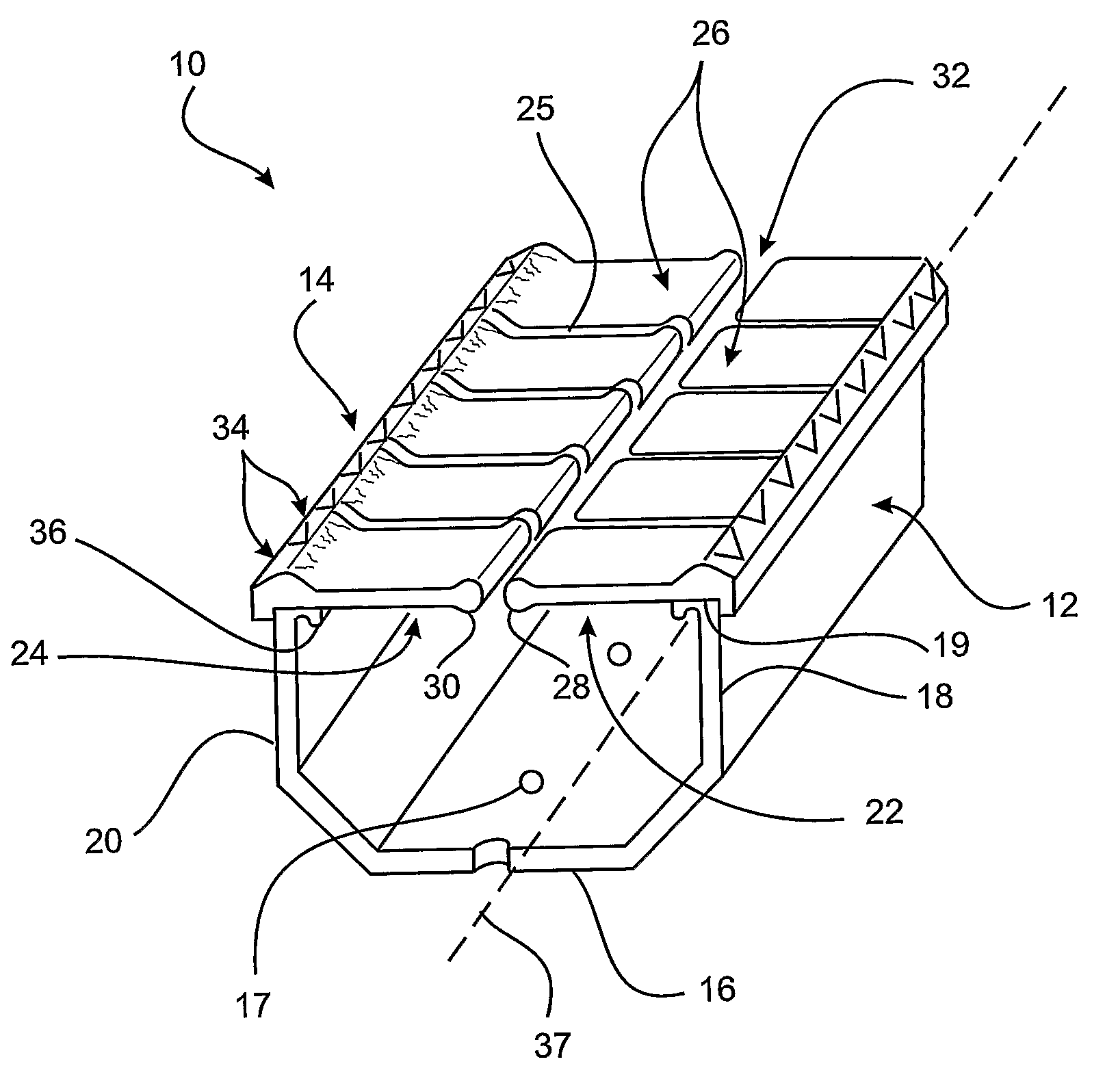
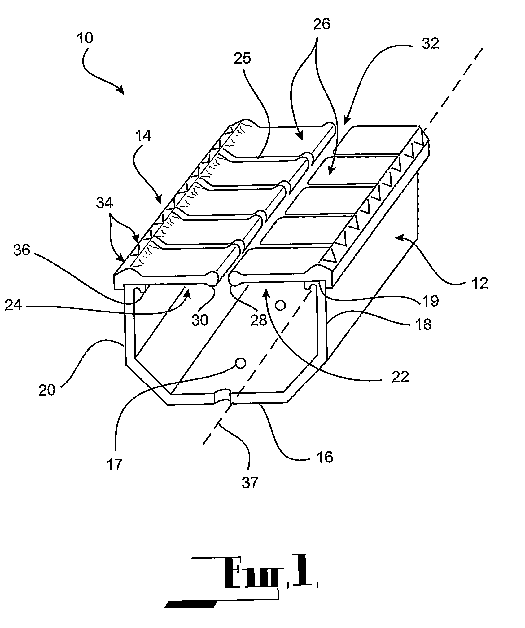
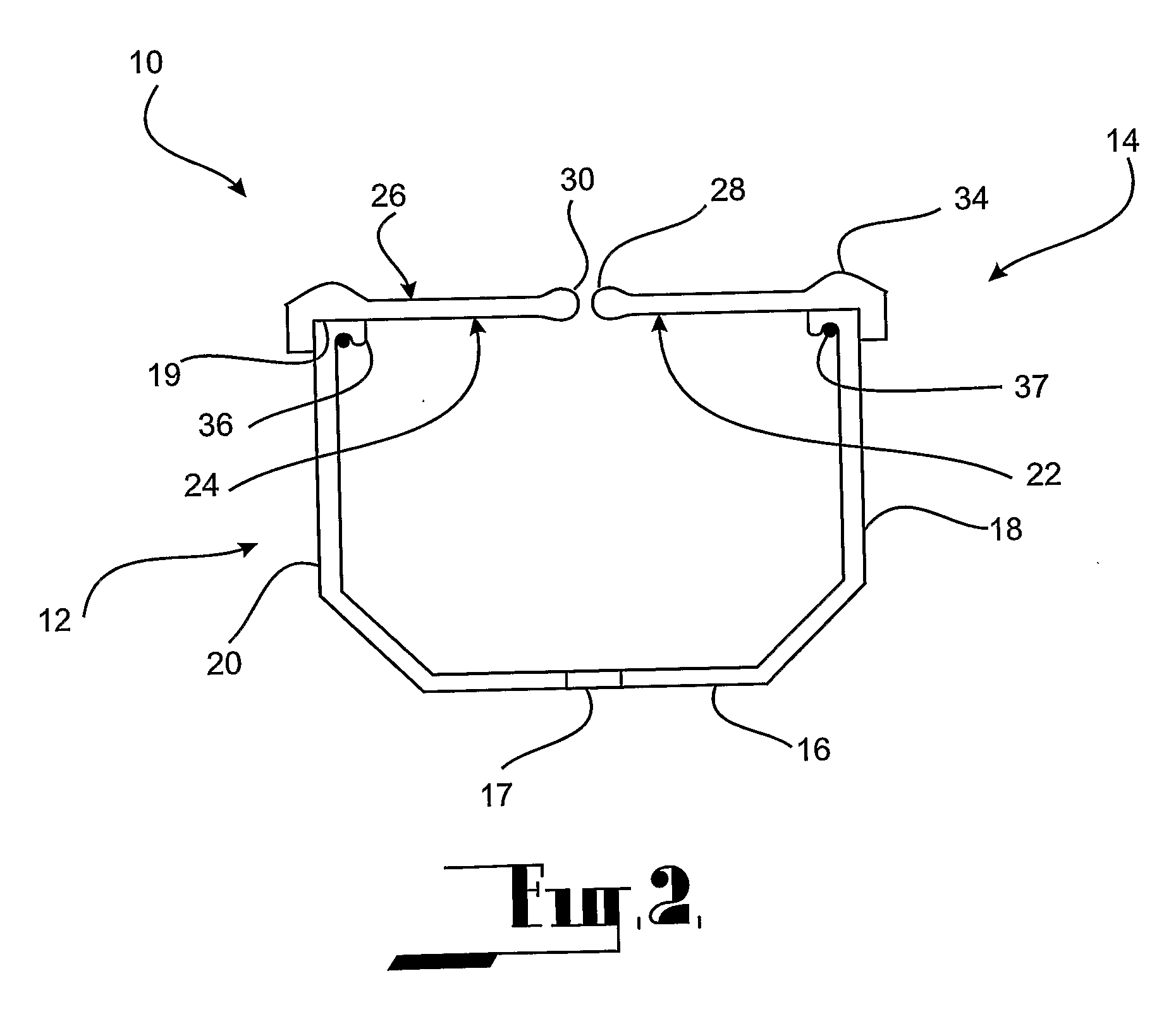
[0045]In FIGS. 1 to 5 there is shown a retaining means 10 in accordance with the present invention. The retaining means 10 comprises an elongate mounting means 12 and a gripping means 14. The mounting means 12 in turn comprises a base 16 connected to both a first support member 18 and a second support member 20. Each of the support members 18 and 20 have an upper edge 19. The base 16 further comprises a number of drainage apertures 17 spaced along its length. The mounting means 12 is formed from a rigid material, for example steel, aluminium or moulded plastic.

[0046]The gripping means 14 comprises a first gripping portion 22 formed from a flexibly resilient material which is attached to the mounting means 12 via the first support member 18 and extends laterally towards a second gripping portion 24 attached to the second support member 20. The second gripping portion 24 is also formed from a flexibly resilient material. The gripping means 14 is attached to the support members 18 and ...

second embodiment

[0053]In FIGS. 6 to 10 there is shown a retaining means 60 in accordance with the present invention. The retaining means 60 is substantially similar to the retaining means 10 and like numerals denote like parts.

[0054]Specifically, FIGS. 7 and 8 depict the mounting means 12 of the retaining means 60. The upper edge 19 of the first and second support members, 18 and 20, comprise an integrated slot 62, for example in the form of a “T” slot. The slot 62 enables the gripping means 14 to engage with the mounting means 12.

[0055]The first and second gripping portions 22 and 24 engage with the slot 62 by way of a foot portion 64 having a substantially complementary shape to the slot 62 such that it can be retained therein, as shown in FIGS. 6, 9 and 10. It is envisaged that the slot 62 and the foot portion 64 may be provided in various complimentary shapes without departing from the spirit and scope of the present invention.

[0056]In FIG. 11 there is shown a bracket 70 for use with the second...


PUM


Abstract

A retaining means comprising: an elongate mounting means; a gripping means; the gripping means comprising a first and second gripping portion, at least one of which is formed at least in part from a flexibly resilient material; each gripping portion being attached to the mounting means; and the first gripping portion having an outer edge positioned in close spatial arrangement with an outer edge of a second gripping portion such that an article may be retained between the outer edge of the first and second gripping portions.

Description

FIELD OF THE INVENTION[0001]The present invention relates to a retaining means. More particularly, the retaining means of the present invention is intended to substantially eliminate the requirement for separate pegs or clips to secure items to be retained therein.BACKGROUND ART[0002]A number of prior art documents disclose a means for retaining items that is configured in an attempt to avoid the requirement for pegs or clips. German Patent DE 3105051 discloses a U-shaped rail which retains the item via a pinching action between two legs of the rail. However, this item is not intended to be used in conjunction with an existing structure, for example a clothes line. Further, given the nature of the pinching mechanism, being constructed from rigid material, inserting the item to be retained may be complicated and result in an operator's fingers being caught or pinched.[0003]Australian Patent 646352 discloses a pegless clothes line which is constructed from a number of plastic links th...

Claims


Application Information

Patent Timeline
IPC IPC(8): D06F57/00D06F55/00A44B99/00
CPCD06F55/00Y10T24/44017Y10T24/44641
Inventor ARCARO, DINO
Owner ARCARO DINO
Why Eureka
Try Eureka