Electronic Apparatus

a technology of electronic equipment and cooling device, which is applied in the direction of electrical apparatus casing/cabinet/drawer, instrument, and semiconductor/solid-state device details, etc., can solve the problems of difficult supply of sufficient air flow to the heat generating device, and achieve the effect of convenient discharge of air flow, convenient use, and sufficient air flow

Active Publication Date: 2010-10-07
SONY COMPUTER ENTERTAINMENT INC
View PDF12 Cites 32 Cited by
  • Summary
  • Abstract
  • Description
  • Claims
  • Application Information

AI Technical Summary

Benefits of technology

[0009]According to the present invention, it is also possible to supply sufficient air flow to the heat generating device.
[0010]Further, according to one aspect of the present invention, the wall member is arranged surrounding the air passage. According to this aspect, it is possible to supply a larger amount of air flow to the heat generating device.
[0011]Further, according to another aspect of the present invention, the electronic apparatus further includes: a housing forming an outer surface of the electronic apparatus; and an air outlet through which the air in the housing is discharged to the outside of the housing. Still further, the wall member forms the outerwall defining the air passage extending from the cooling unit to the air outlet. According to this aspect, it is possible to smoothly discharge the air flow having passed the heat generating device that warms up to the outside of the housing.
[0013]Further, according to still another aspect of the present invention, the air passage includes a main passage through which an air flow for cooling the heat generating device flows, and a bypass passage partitioned from the main passage. According to this aspect, it is possible to improve the ventilation efficiency.

Problems solved by technology

Therefore, it is sometimes difficult to supply a sufficient air flow to the heat generating device.

Method used


Image

  • Electronic Apparatus
  • Electronic Apparatus
  • Electronic Apparatus

Examples


Embodiment Construction

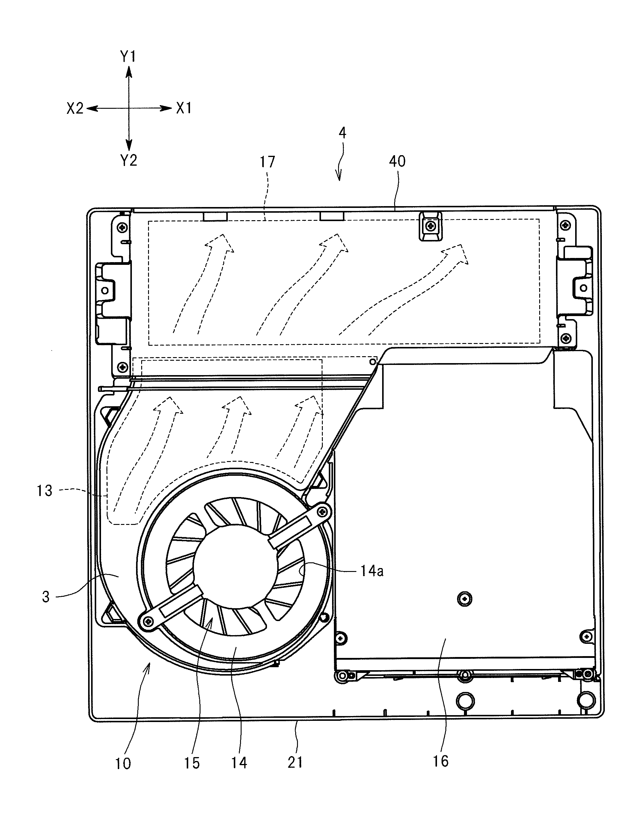
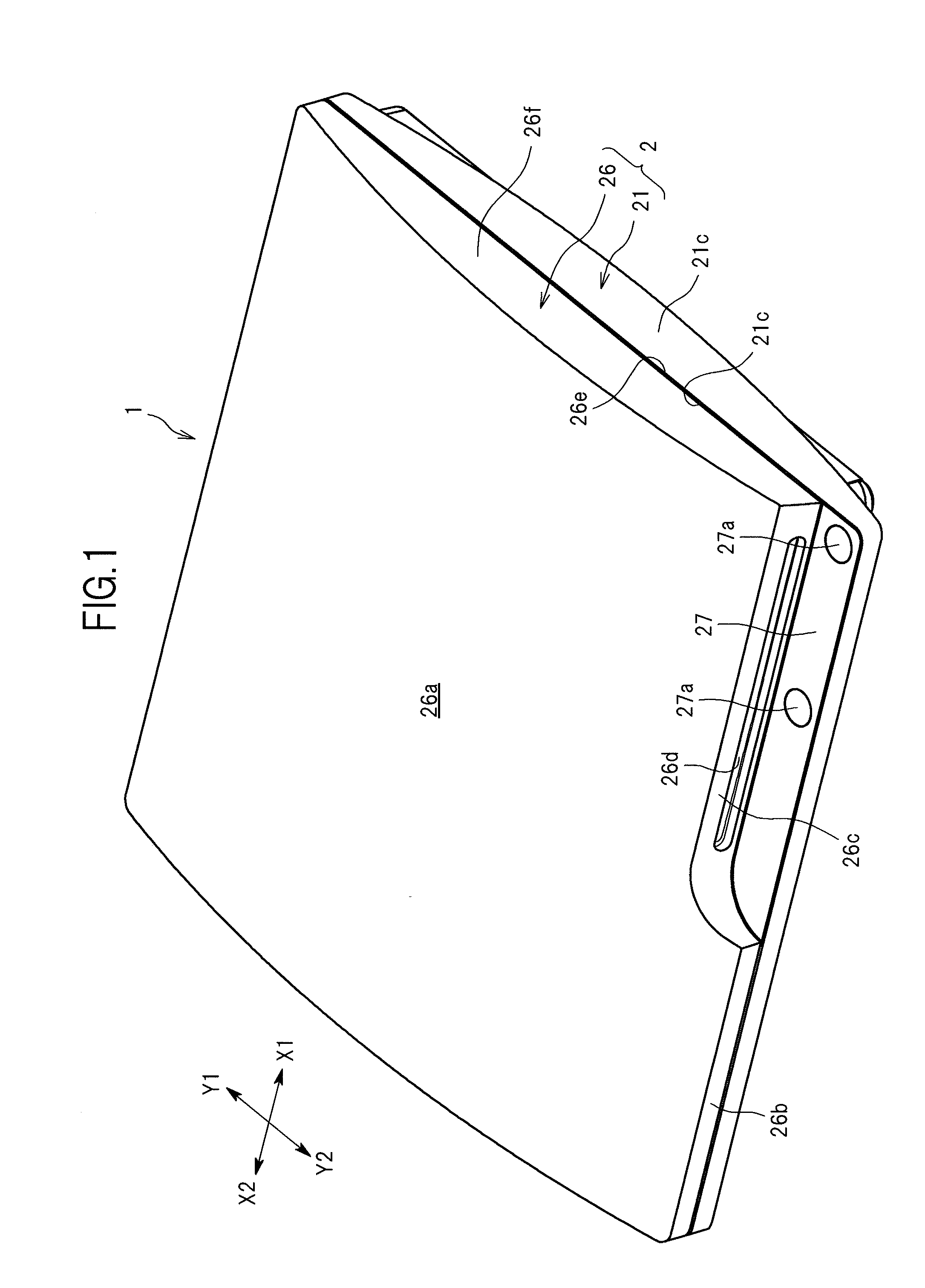
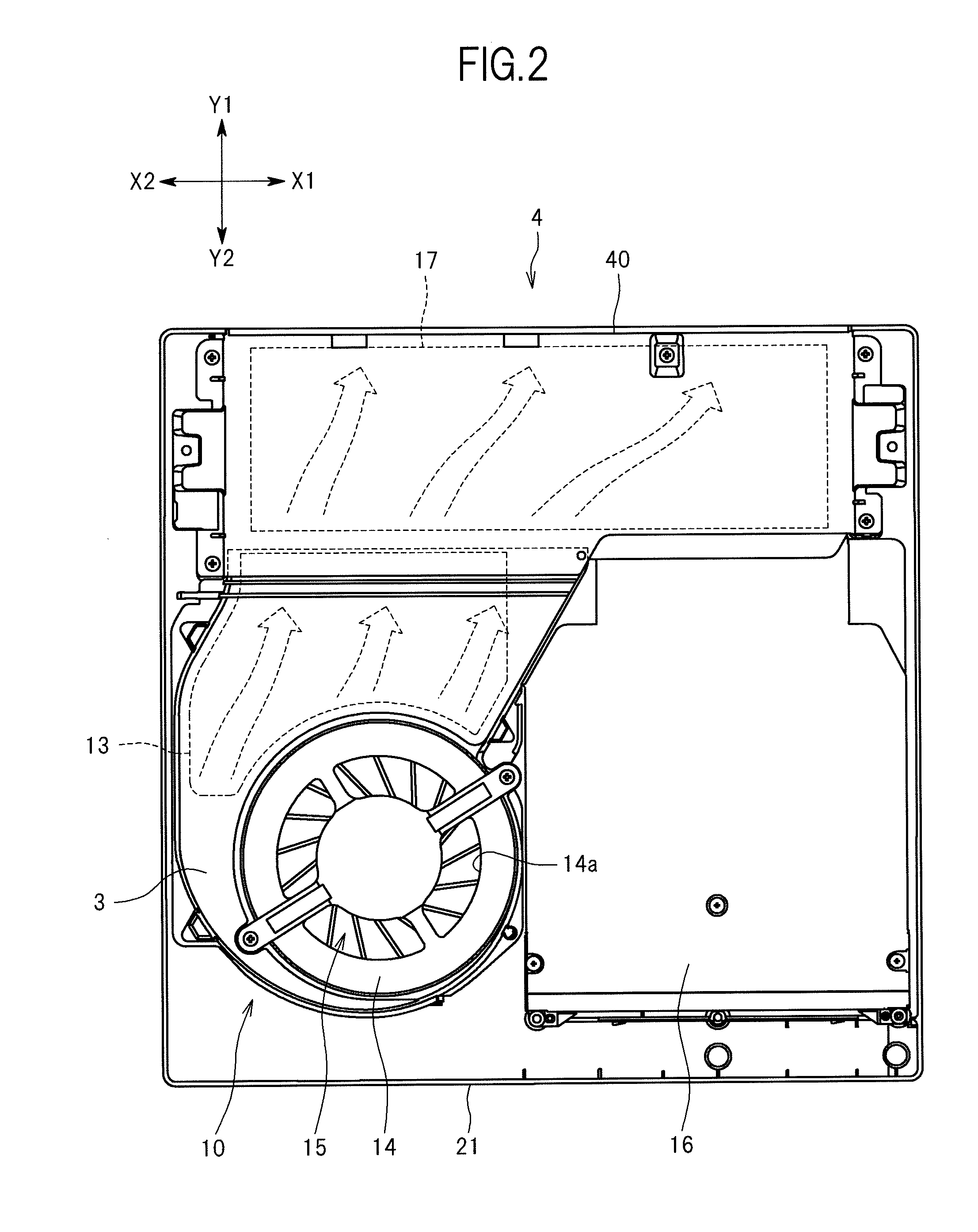
[0028]An embodiment of the present invention is described below. FIG. 1 is a perspective view of an electronic apparatus 1 as an example according to the embodiment of the present invention. FIG. 2 is a plan view of the electronic apparatus 1 in a state in which an upper housing 26 is detached therefrom. FIG. 3 is a bottom view of the electronic apparatus 1. FIG. 4 is a back view of the electronic apparatus 1. FIG. 5 is a plan view of a cooling unit 10 of the electronic apparatus 1 and a power circuit case 4 housing a power circuit 17. FIG. 6 is an exploded perspective view of the cooling unit 10. FIG. 7 is an exploded perspective view of power circuit case 4. FIG. 8 is a front view of an upper wall member 40 constituting the power circuit case 4. FIG. 9 is a sectional view taken along the line IX-IX of FIG. 5. FIG. 10 is an enlarged view of FIG. 9. FIG. 11 is a sectional view taken along the line XI-XI of FIG. 5. FIG. 12 is an enlarged view of FIG. 11. In this regard, in FIGS. 7, 1...


PUM


Abstract

Provided is an electronic apparatus capable of also supplying sufficient air flow to a heat generating device other than the heat sink. An electronic apparatus includes: a cooling unit (10) including a heat sink (13), and a cooling fan (15) for generating air flow for receiving heat of the heat sink (13); an upper wall member (40) connected to the cooling unit (10) so as to form an outer wall defining an air passage continuous with the cooling unit (10); and a power circuit (17) arranged in the air passage and serving as an object to be cooled.

Description

CROSS-REFERENCE TO RELATED APPLICATION[0001]The present application claims priority from Japanese patent application No. 2009-090572 filed on Apr. 2, 2009, the content of which is hereby incorporated by reference into this application.BACKGROUND OF THE INVENTION[0002]1. Field of the Invention[0003]The present invention relates to technology for improving cooling performance for a device installed in an electronic apparatus.[0004]2. Description of the Related Art[0005]There is available an electronic apparatus, such as a game device, a personal computer, and audio-visual equipment, which includes a heat sink and a cooling fan for generating air flow receiving heat of the heat sink. In an electronic apparatus disclosed in JP 2004-119621 A, a cooling fan is adjacent to a heat sink, so that air flow generated by the cooling fan flows through the heat sink while hardly diffusing. With this configuration, it is possible to obtain a satisfactory cooling effect for the heat sink.[0006]Besid...

Claims


Application Information

Patent Timeline
Patent Type & Authority Applications(United States)
IPC IPC(8): H05K7/20
CPCH05K7/20163H05K7/20145
Inventor IKEDA, KENSUKE
Owner SONY COMPUTER ENTERTAINMENT INC
Why Eureka
Try Eureka