Heat exchanger

A technology of heat exchanger and heat dissipation module, which is applied in the cooling of instruments, components of instruments, instruments, etc. It can solve the problems of blocking the opening of the flow channel, unable to provide air volume, and increasing the height of the box.

Active Publication Date: 2012-07-18
DELTA ELECTRONICS INC
View PDF6 Cites 4 Cited by
  • Summary
  • Abstract
  • Description
  • Claims
  • Application Information

AI Technical Summary

Problems solved by technology

thus increasing the height of the box
Moreover, when the thickness of the existing heat exchanger is reduced, the opening of the flow channel of the heat dissipation module is also reduced, and the opening of the f

Method used


Image

  • Heat exchanger
  • Heat exchanger
  • Heat exchanger

Examples


Embodiment Construction

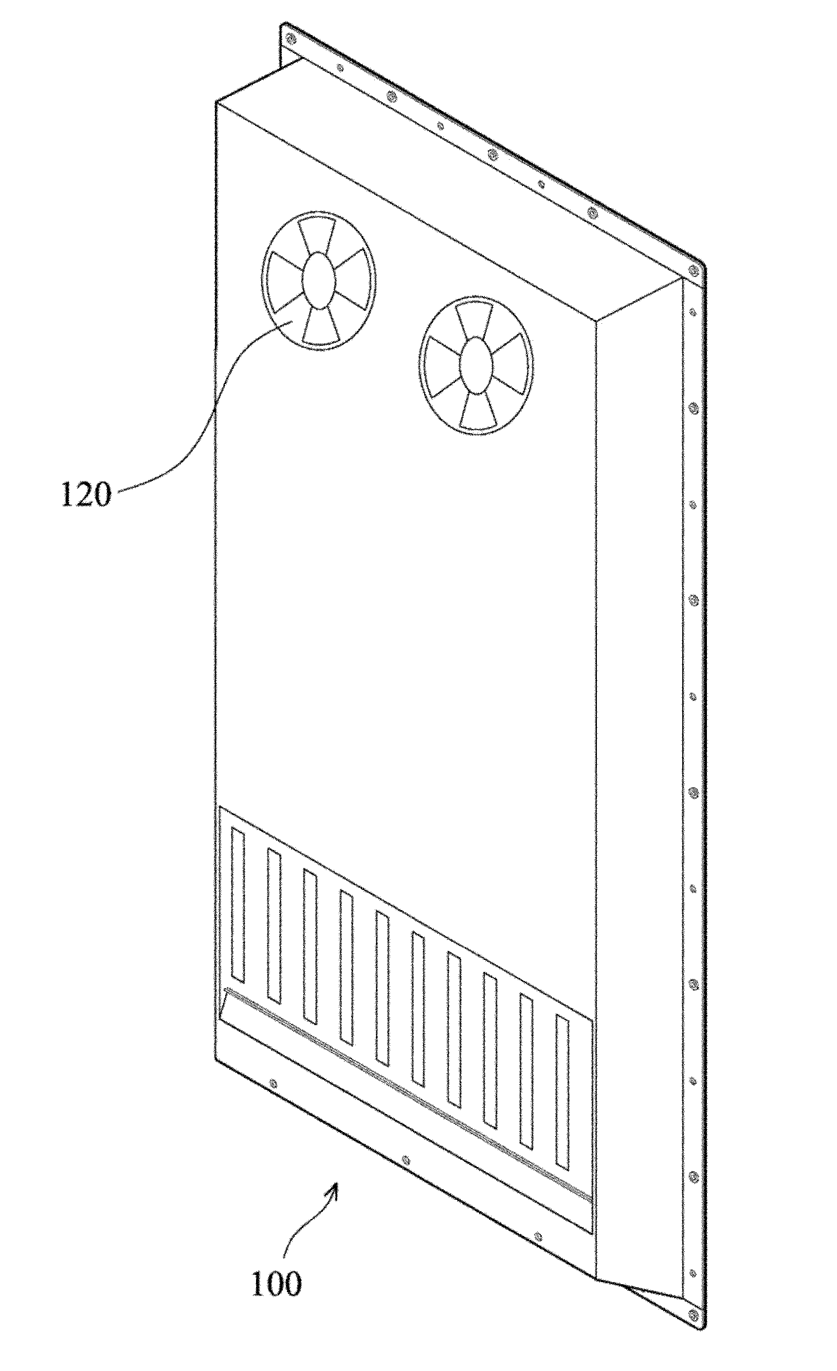
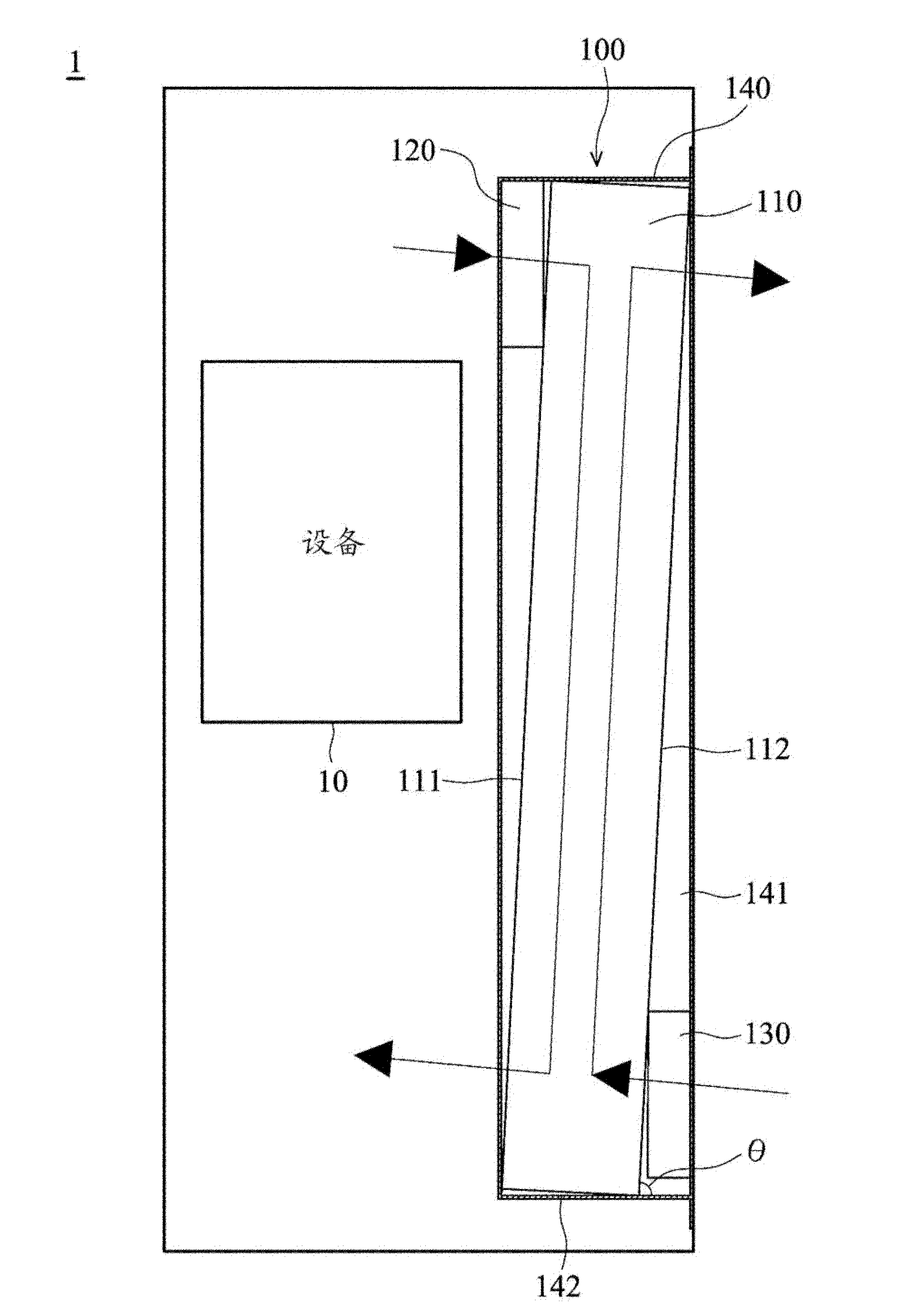
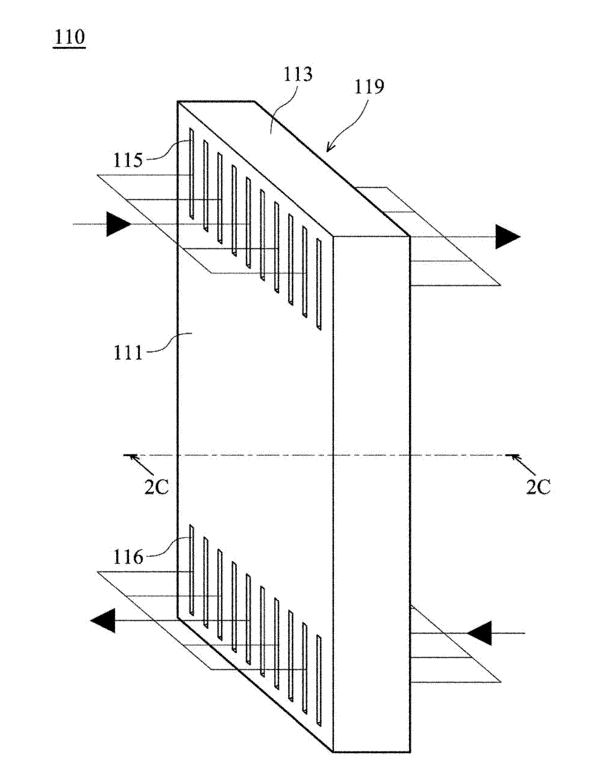
[0034] Figure 1A is a perspective view showing a heat exchanger 100 according to an embodiment of the present invention. Figure 1B It shows the situation where the heat exchanger 100 according to the embodiment of the present invention is installed in a target system 1 . refer to Figure 1A , Figure 1B , the heat exchanger 100 of the embodiment of the present invention includes a heat dissipation module 110 , an inner circulation fan 120 , an outer circulation fan 130 and a box 140 . refer to Figure 2A , Figure 2B The cooling module 110 includes a module body 119, a plurality of first air inlets 115, a plurality of first air outlets 116, a plurality of second air inlets 117, a plurality of second air outlets 118, a plurality of first flow channels 1101 and a plurality of a second flow channel 1102. collocation reference Figure 2C , which is displayed Figure 2A 2C-2C in the sectional view, the plurality of first flow channels 1101 and the plurality of second flow c...


PUM


Abstract

The invention discloses a heat exchanger, which comprises a heat dissipation module, an internal circulation fan and an external circulation fan. The heat dissipation module comprises a module body, a plurality of first air inlets, a plurality of first air outlets, a plurality of second air inlets, a plurality of second air outlets, a plurality of first runners and a plurality of second runners. The plurality of first air inlets and the plurality of first air outlets are respectively communicated with the plurality of first runners. The plurality of second air inlets and the plurality of second air outlets are respectively communicated with the plurality of second runners. The module body comprises a first surface and a second surface, and the first surface is opposite to the second surface. The plurality of first air inlets and the plurality of first air outlets are located on the first surface, and the plurality of second air inlets and the plurality of second air outlets are located on the second surface.

Description

technical field [0001] The invention relates to a heat exchanger, in particular to an air-cooled heat exchanger. Background technique [0002] The existing heat exchanger includes a box body, a cooling module, an internal circulation fan and an external circulation fan. The heat dissipation module, the internal circulation fan and the external circulation fan are all arranged in the cabinet. In the prior art, the flow channel openings of the heat dissipation module are usually located on the top and bottom surfaces of the heat dissipation module. Therefore, the internal circulation fan and the internal circulation fan need to be respectively arranged above and below the heat dissipation module. Thus increasing the height of the cabinet. Moreover, when the thickness of the existing heat exchanger is reduced, the opening of the flow channel of the heat dissipation module is also reduced, and the opening of the flow channel is easily blocked by dust. At the same time, the siz...

Claims


Application Information

Patent Timeline
IPC IPC(8): G12B15/04
Inventor 陈李龙黄建雄涂雅森陈英琦
Owner DELTA ELECTRONICS INC
Why Eureka
Try Eureka