Multi-rotor fan assembly for a cotton picker

a multi-rotor fan and cotton picker technology, applied in the field of cotton picker fans, can solve the problems of shortened life of the fan and its drive, low reliability, and long service life, and achieve the effect of convenient access and openability

Active Publication Date: 2007-01-30
BLUE LEAF I P INC
View PDF18 Cites 3 Cited by
  • Summary
  • Abstract
  • Description
  • Claims
  • Application Information

AI Technical Summary

Benefits of technology

[0007]As a result, each of the picker row units or harvesting units of the cotton harvester can receive an air flow or flows from a dedicated fan, thereby ensuring that the air flow to the individual row units is adequate, and, if the fans and ducts are the same and similarly connected to the row units, the air flows thereto should be about equal.
[0008]As a preferred embodiment for use on a cotton harvesting machine having six picker row units, two of the present fan assemblies are provided in horizontal axial alignment just behind the operator cab of the machine and are rotatably driven by a common power source such as, but not limited to, a belt, shaft or other mechanical drive connected to an output of an engine of the machine, a fluid motor, an electric motor or the like, and the hood or upper enclosure of each of the fan assemblies is easily reachable and openable for accessing the fans.

Problems solved by technology

A disadvantage that has been anticipated, however, is that when additional row units are contemplated, for instance, six or more units including two sets of picking apparatus each, the currently used fans would have to be operated at speeds above those desired to provide the required air flows, which would be expected to result in lower reliability and shortened life of the fans and their drives.
Also, due to the location of the fans within the chassis of the machine, they are more difficult than desirable to access for inspection, maintenance and service, such that, the lower reliability would result in longer downtimes for service.
Still further, it is anticipated that using one fan to provide air flows to three or more picking apparatus could result in uneven or less than desirable air flow to one or more of the apparatus.

Method used


Image

  • Multi-rotor fan assembly for a cotton picker
  • Multi-rotor fan assembly for a cotton picker
  • Multi-rotor fan assembly for a cotton picker

Examples


Embodiment Construction

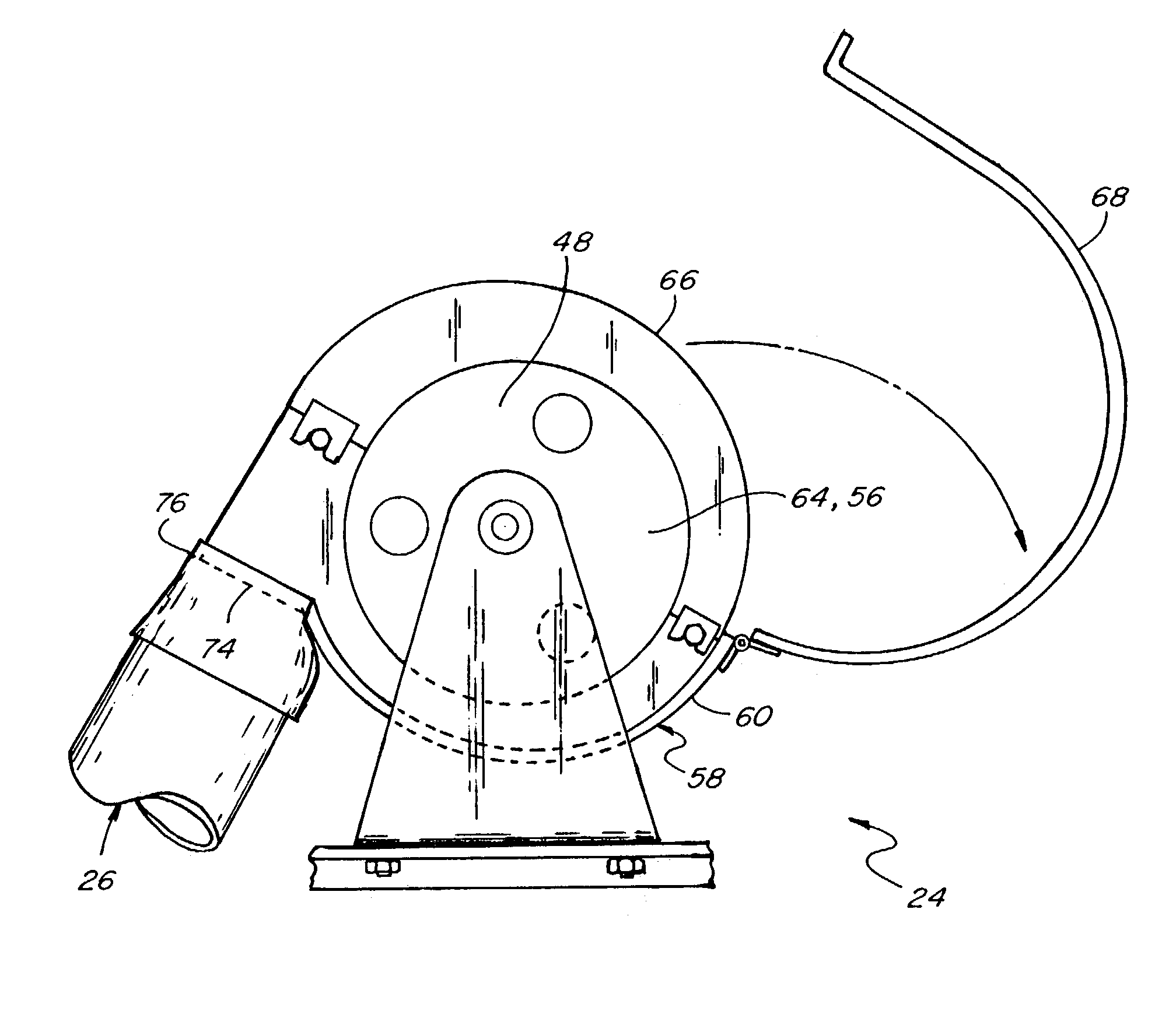
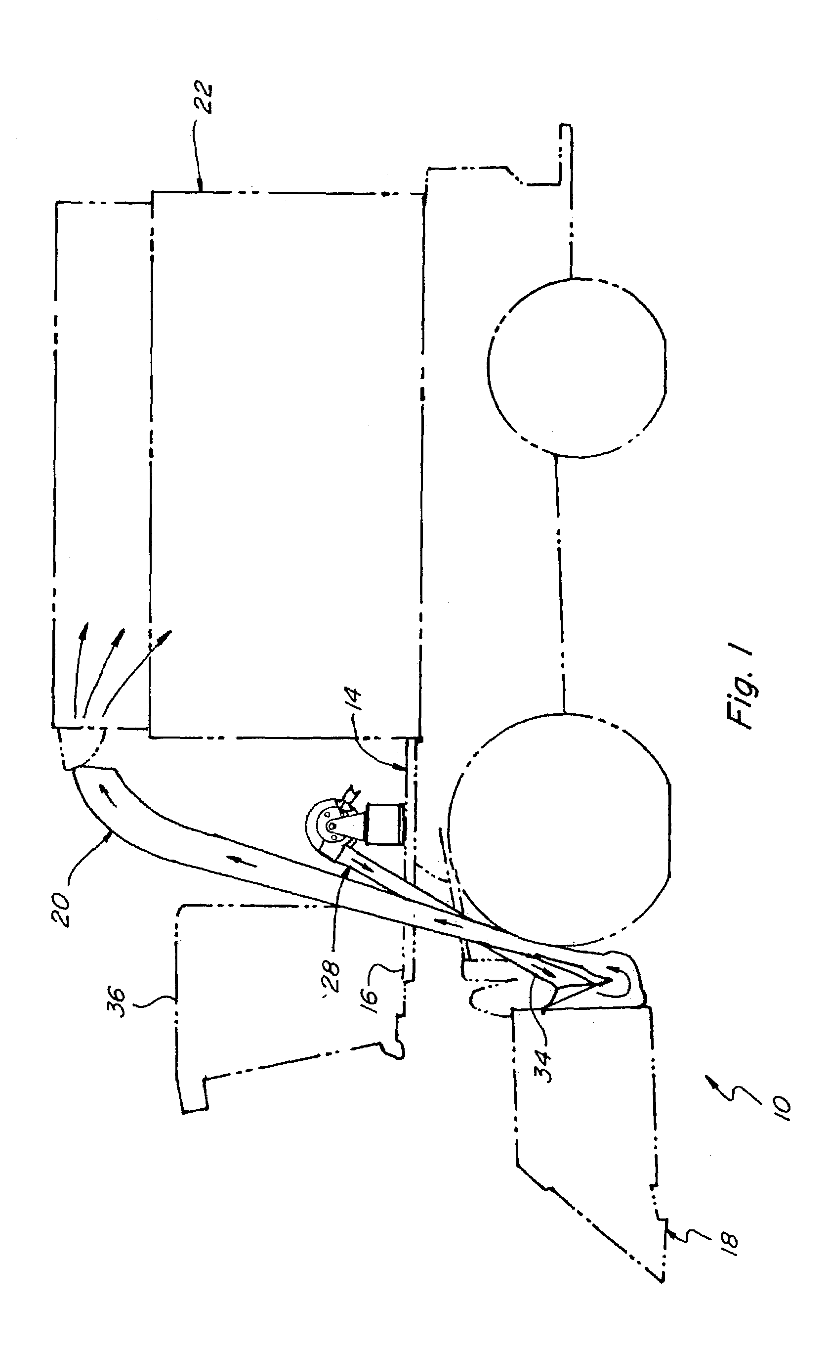
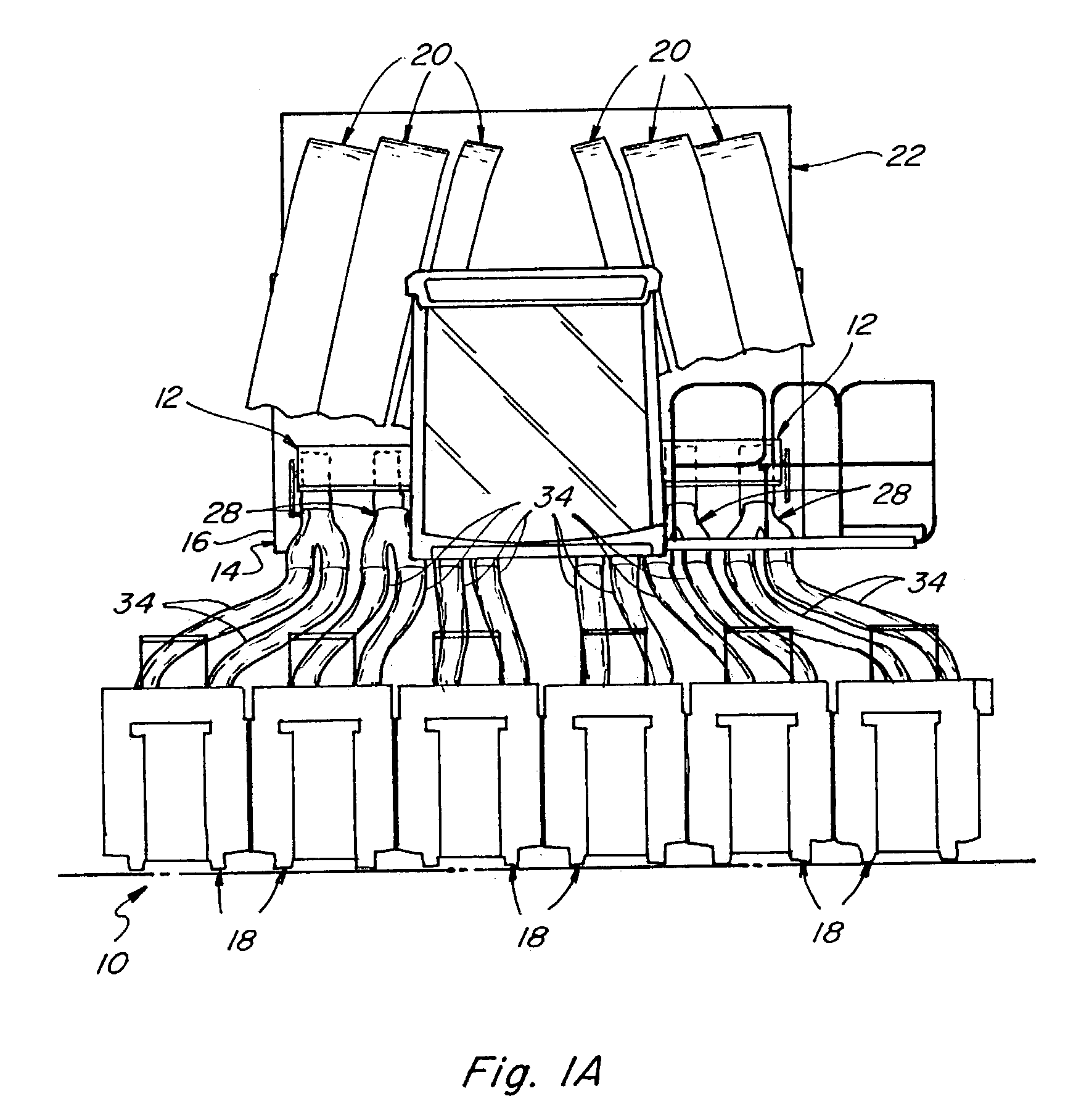
[0016]Referring now to the drawings wherein a preferred embodiment of the present invention is shown, FIGS. 1 and 1A shows a representative self-propelled cotton picking machine 10 of well known, conventional construction, including a pair of multi-rotor blower assemblies 12 constructed and operable according to the teachings of the present invention. Cotton picker 10 generally includes a chassis 14 including a forward end 16 supporting a plurality of cotton harvesting units or picker row units 18 operable for removing cotton from cotton plants as row units 18 are moved forwardly therethrough by picker 10, also in the conventional, well known manner. Each picker row unit 18 generally includes a pair of rotors (not shown) for rotatably driving a plurality of picker spindles through the cotton plants for removing the cotton therefrom, the cotton being removed from the spindles by doffers (also not shown) such that the removed cotton can be carried by continuous flows of air through du...


PUM


Abstract

A multi-rotor blower fan assembly for a cotton picker utilizes a plurality of separate fan enclosures each containing a fan for supplying an individual air flow to a picker unit of the picker, the fans being mounted on a common shaft for rotation therewith, with a unitary removable or openable cover or hood covering access openings of the fan enclosures. One or more of the fan assemblies can be mounted on the picker, for instance, on an existing platform on the picker chassis just rearward of the operator cab, in end-to-end relation, and rotatably driven using a common drive.

Description

TECHNICAL FIELD[0001]This invention relates generally to fans for generating individual air flows to cotton picker row units of cotton harvesting machines for conveying harvested cotton from the row units to a container, and more particularly, to a fan assembly utilizing multiple rotors having lower portions contained in individual lower fan housings for receiving and providing individualized air flows to the row units, and upper portions contained in or covered by a common upper housing section or hood, to provide easy access to the fans for inspection, maintenance and service.BACKGROUND ART[0002]Currently, self-propelled cotton picking machines typically include several picker row units or harvesting units which are driven by the machine through a cotton field for harvesting cotton from the cotton plants. Essentially, the cotton is removed from the plants by rotating spindles of the row units, and the cotton is removed from the individual spindles by devices known as doffers. Afte...

Claims


Application Information

Patent Timeline
Patent Type & Authority Patents(United States)
IPC IPC(8): A01D46/08
CPCA01D46/08
Inventor LUKAC, J. BRADLEYTENBRINK, SCOTT W.SHILLINGTON, STEVEN C.
Owner BLUE LEAF I P INC
Why Eureka
Try Eureka