Method and apparatus for feeding in and handling waste material

a technology of waste material and feeding method, which is applied in the direction of bulk conveyors, domestic applications, refuse gathering, etc., can solve the problems of large space requirement of intermediate containers, high excavation costs, and large space requirements of intermediate containers, so as to increase the capacity of input points, reduce energy consumption of conveying systems, and increase waste

Active Publication Date: 2019-09-03
MARICAP OY
View PDF73 Cites 5 Cited by
  • Summary
  • Abstract
  • Description
  • Claims
  • Application Information

AI Technical Summary

Benefits of technology

[0013]The solution according to the invention has a number of important advantages. By means of the invention the compacting, i.e. compressed size, of the waste material is achieved, in which case more material than earlier fits into the intermediate container. The compression in size can, depending on the application site, be in the region of 30-70%, depending on the type of waste and on the type of recycleable material. An intermediate container can also be disposed in a horizontal attitude or it can comprise a horizontal section, in which case a deep installation pit is not needed for it, but instead a conventional excavation depth can be used for the waste conveying piping. By arranging the channel section of the intermediate container of one material category to be such that the channel sections of the intermediate container of at least one other input point, typically of all the input points of the feed-in station, connect to it, a collection piping assembly is achieved wherein the intermediate container of the material category requiring most intermediate container volume can be formed, on the one hand, in a shallow space, but however large in volume. In this case the number of input points for the material category can at the same time be limited. Compression of the material is thus achieved as the combined effect of replacement air and of the suction brought about by a partial-vacuum generator of the pneumatic conveying system for wastes when the material is compressed against an impediment. The impediment can be a means arranged between the intermediate container section and the conveying pipe, through which or around the sides of which means an air flow is able to travel. The impediment acts on the material by bringing about a support effect in it, which mainly prevents, to at least a significant extent, the passage of the material past or through the impediment. With the solution according to the invention an intermediate container of the desired size can be achieved, the material being fed into which container can be compressed in size by means of one or more impediments and an air flow. The entry of replacement air can be regulated e.g. with a separate replacement air valve arranged in the container part of an input point. By opening and closing the replacement air valve, the start of movement of material in the intermediate container can be regulated. By arranging a replacement air valve to open and close the pathway of replacement air, the flow cross-sectional area of which is smaller than the flow cross-sectional area of the channel part to which it is connected and from which the suction acts, a sufficient replacement air flow for compression is achieved. At the same time the material of the intermediate containers of a number of input points can be compressed, i.e. compacted, simultaneously, in which case considerable savings in time and energy are achieved. The compression can be performed at least partly at the same time as material is conveyed from some other input point or intermediate container of the system. A separate replacement air valve can also be used as a pilot valve, i.e. by opening first the replacement air valve and only then the discharge valve or larger shut-off means. In this case a possible pressure shock and / or noise problem can be reduced. Another advantage achieved is that opening of the actual discharge valve is possible with a smaller force than without a pilot valve. According to one embodiment the impediment is a force-receiving means arranged in the container space of the intermediate container, which means can be placed into the container space and displaced out of it with a drive device. Depending on the application site, the impediment can also be a shaper of the material, e.g. a formatter. According to one embodiment of the invention means for bringing replacement air into the vicinity of the impediment can be arranged in connection with an impediment, at least when material is conveyed in the conveying piping after the removal of the impediment. In this case replacement air can be brought into the bulk of material being conveyed, which boosts the conveying efficiency of material in the conveying pipe. In the method according to the invention material categories can be efficiently conveyed with an arrangement wherein, in the displacements of a number of material categories, a material category that cleans the conveying piping is conveyed now and then, e.g. after biodegradable waste paperboard is conveyed, or after mixed waste paper is conveyed.

Problems solved by technology

One drawback, among others, of prior art solutions is that the space requirement of an intermediate container, especially when an input pipe is used as an intermediate container, is large.
The excavation work is expensive, particularly in rocky areas where blasting is required for achieving a trench.

Method used


Image

  • Method and apparatus for feeding in and handling waste material
  • Method and apparatus for feeding in and handling waste material
  • Method and apparatus for feeding in and handling waste material

Examples


Embodiment Construction

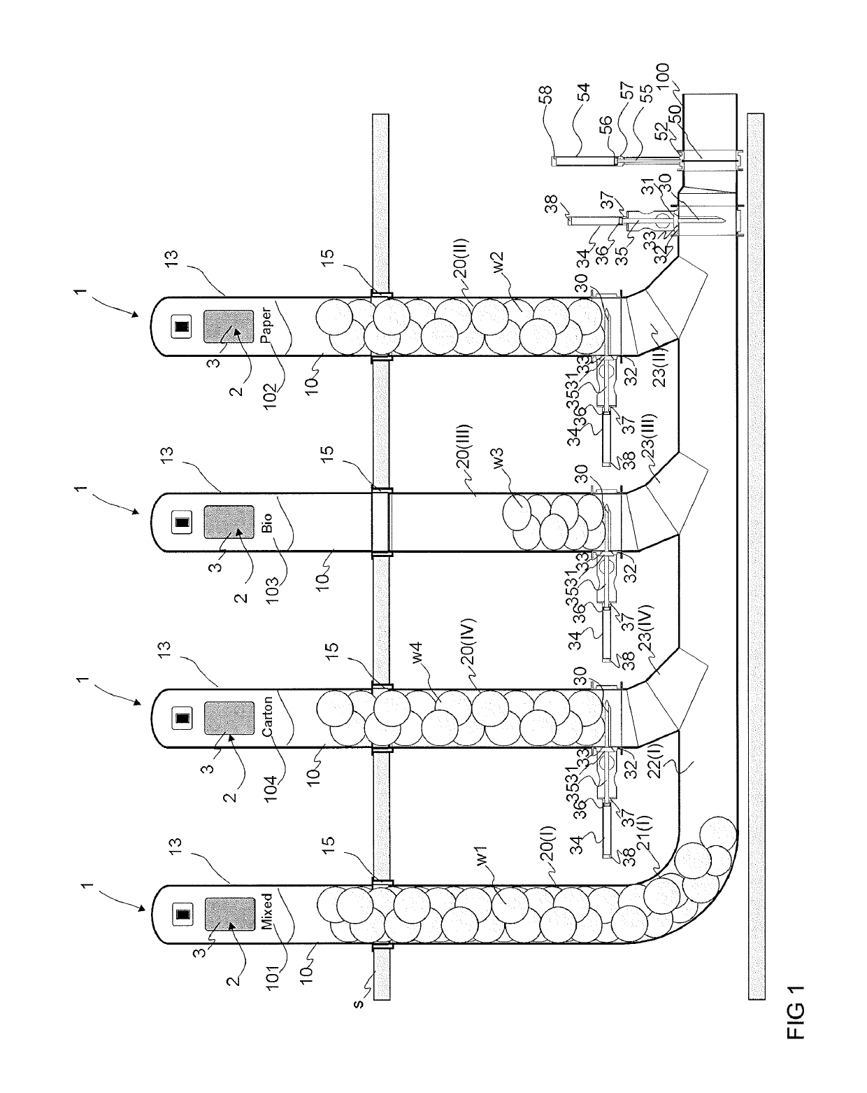
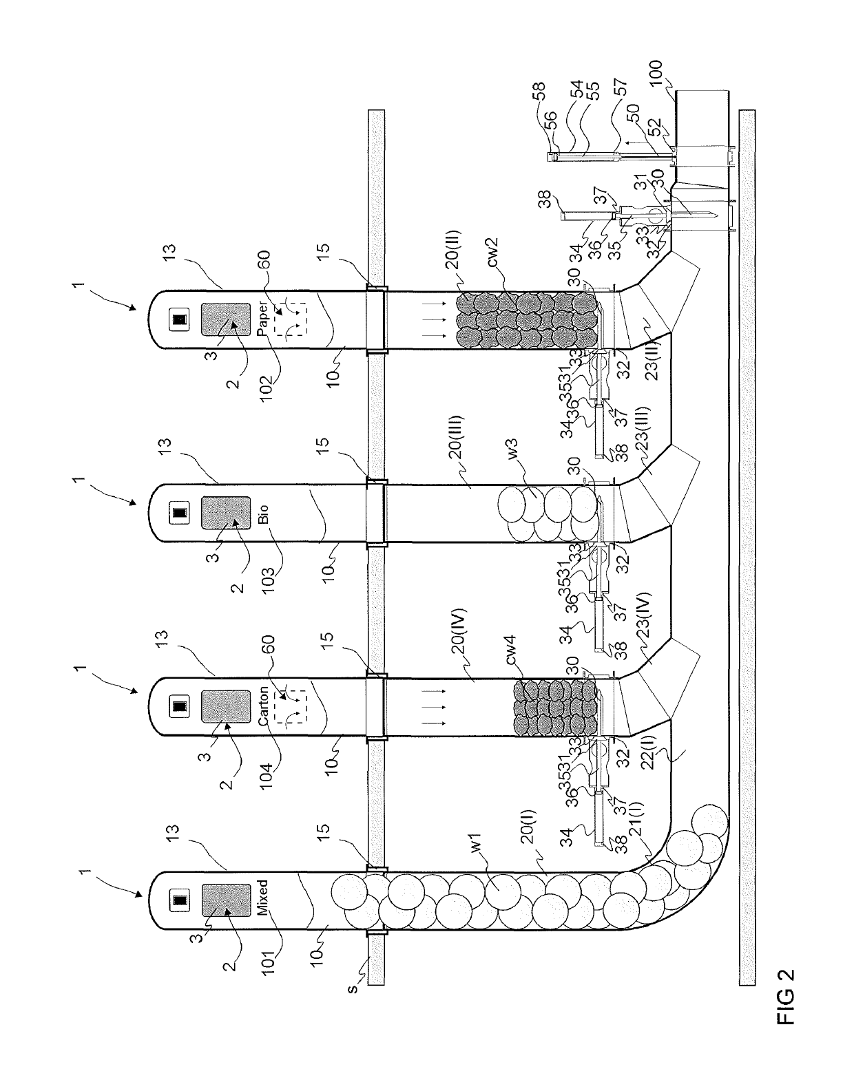
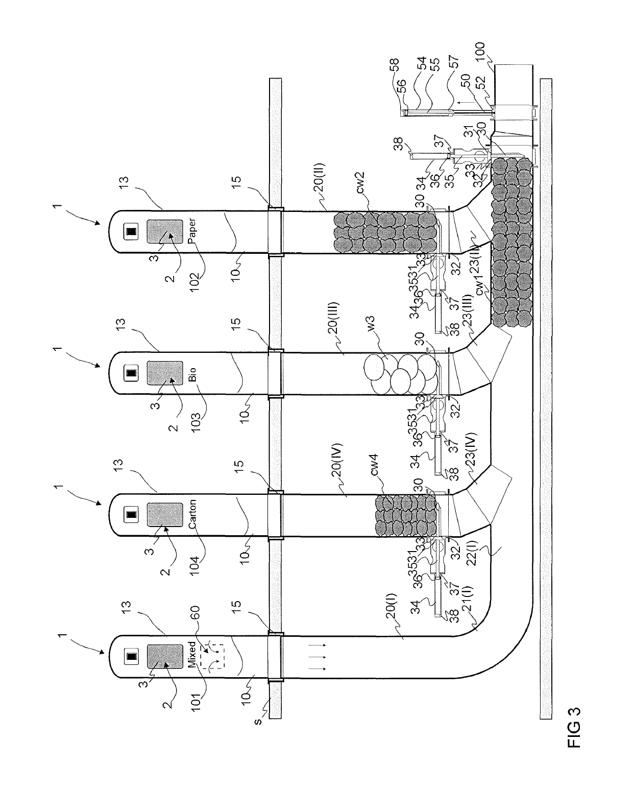
[0032]FIGS. 1-8 present a simplified view of an apparatus according to the invention. The apparatus typically comprises at least one feed-in station, which comprises a number of input points 1. FIGS. 1-8 present a feed-in station of a pneumatic pipe transport system for wastes, which station comprises at least two input points 1. In the embodiment of the figure there are four input points 1. The input points 1 are typically for a number of different categories of material. FIGS. 1-8 thus present four input points 1, each of which in the embodiment of the figure is intended for a different category of material. Depending on the application site, there can be more or fewer input points in the feed-in station. Also there can be a higher or lower number of material categories intended for feeding into the input points 1 of the feed-in station. The input points 1 intended for different material categories are marked in the figures with the different reference numbers 101, 102, 103, 104. ...


PUM


Abstract

Method for feeding in and for handling waste material in the channel section of a pneumatic wastes conveying system, in which method waste material or recycleable material is fed into a feed-in container (10) from the input aperture (2) of at least two input points (1) of a pneumatic pipe transport system for material and onwards into the channel section (20, 21, 22) between the feed-in container and the material conveying pipe (100), from where the material is conveyed along with the transporting air via the material conveying pipe (100) to the delivery end of the pneumatic material conveying system, where the material is separated from the transporting air. In the method the channel section (20(II), 20(III), 20(IV) . . . (22(II), (22(III), 22(IV)) of at least one second input point is connected to the channel section (20(I), 21(I), 22(I)) of one first input point between the input point (1) and an impeding means (30, 30'), in that in the method at least a part of the material (w1, w2, w3, w4) fed in is acted upon by the combined effect of suction and replacement air in the channel section (20(I), 21(I), 22(I) . . . (20(IV), 21(IV), 22(IV)) by bringing about compression in size in at least a part of the material (w1, w2, w3, w4) being conveyed, by means of an impediment (30) arranged between the conveying pipe (100) and the material (w1, w2, w3, w4) to be handled, or against the impediment, before transportation of the material to the delivery end of the pneumatic transport system for wastes.

Description

CROSS-REFERENCE OF RELATED APPLICATIONS[0001]This application is a National Phase of International Patent Application No. PCT / FI2014 / 050597, filed on Jul. 29, 2014, which claims the benefit under 35 U.S.C. § 119(a) to Finland Patent Application Nos. 20135801, filed on Jul. 30, 2013, and 20136141, filed on Nov. 18, 2013, all of which are hereby expressly incorporated by reference into the present application.FIELD OF THE INVENTION[0002]The object of the invention is a method for feeding in and for handling waste material in the channel section of a pneumatic waste conveying system.[0003]Another object of the invention is an apparatus for feeding in and for handling waste material in the channel section of a pneumatic waste conveying system.[0004]The invention also relates to a system that uses the apparatus for feeding in and for handling waste material in the channel section of a pneumatic waste conveying system.BACKGROUND OF THE INVENTION[0005]The invention relates generally to mat...

Claims


Application Information

Patent Timeline
Patent Type & Authority Patents(United States)
IPC IPC(8): B65G53/28B65G53/46B65F1/10B65F5/00
CPCB65F5/005B65F1/10B65G53/46B65G53/4691B65G53/4608B65G53/52B65F5/00
Inventor SUNDHOLM, GÖRANSUNDHOLM, GORAN
Owner MARICAP OY
Why Eureka
Try Eureka