
High-pressure rotary valve

A rotary valve and high-pressure technology, which is applied in the field of high-pressure rotary valves, can solve the problems that the processing and feeding device cannot transport materials into the interior of the equipment, and cannot quickly and conveniently realize feeding, so as to achieve the effect of high material transportation efficiency and convenient operation

Pending Publication Date: 2019-05-03
上海敏杰制药机械有限公司
View PDF0 Cites 0 Cited by
  • Summary
  • Abstract
  • Description
  • Claims
  • Application Information

AI Technical Summary

Problems solved by technology

[0003] However, in the prior art, there is often a situation where the internal pressure of the equipment is higher than the pressure at the outlet of the hopper. At this time, due to the positive pressure difference, the conventional feeding device cannot smoothly transport the material into the equipment for processing, resulting in Infeed cannot be achieved quickly and easily

Method used


Image

  • High-pressure rotary valve
  • High-pressure rotary valve
  • High-pressure rotary valve

Examples


Embodiment Construction

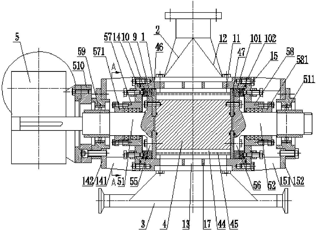
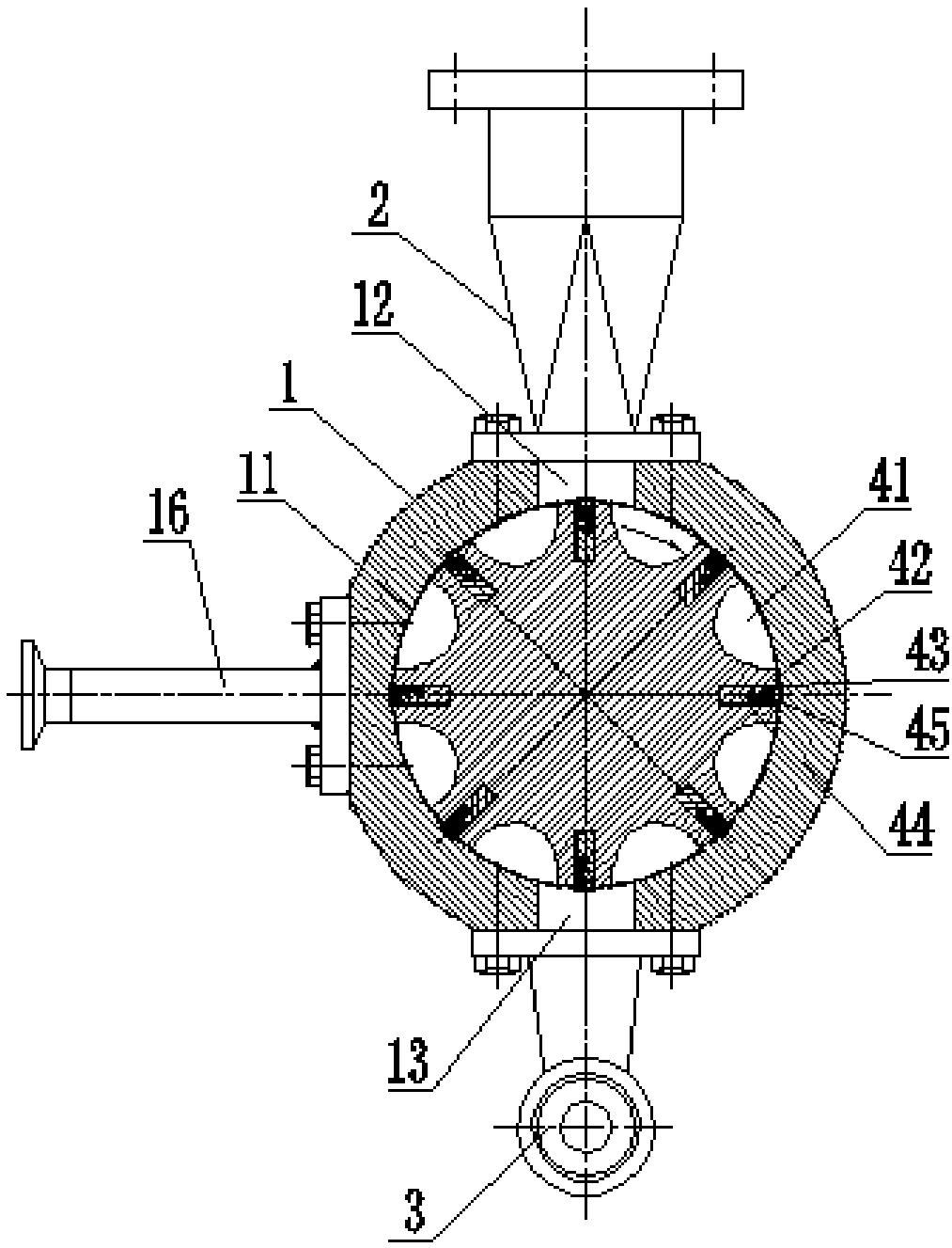
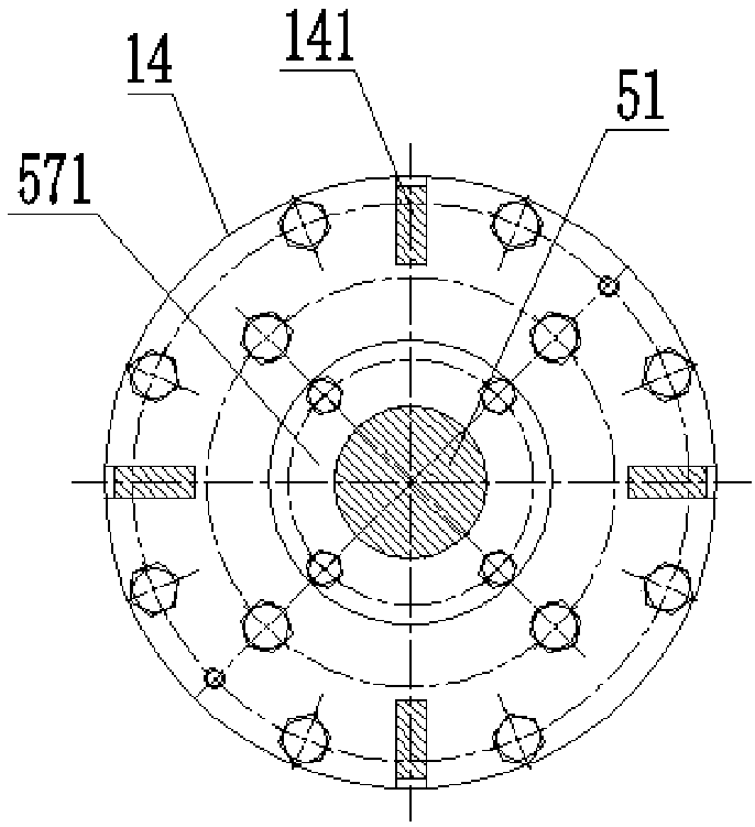
[0036] The high-pressure rotary valve of the present invention will be further described in detail with specific embodiments below in conjunction with the accompanying drawings. It should be understood that the following examples are only used to illustrate the present invention but not to limit the scope of the present invention.

[0037] Such as Figure 1 to Figure 3 As shown, according to the first embodiment of the present invention, the high-pressure rotary valve of the present invention includes a cylindrical valve body 1, and the interior of the valve body 1 has an inner cavity 11 with a circular cross section, and the valve body The top of 1 is provided with an inlet 12, the inlet 12 is connected to the feed pipe 2, and the bottom is provided with an outlet 13, and the outlet 13 is connected to the outlet pipe 3, and the pressure in the outlet pipe 3 is high For the pressure in the feed pipe 2 , the pressure at the outlet 13 is higher than the pressure at the inlet 12...


PUM


Abstract

The invention provides a high-pressure rotary valve which comprises a valve body, wherein an inner cavity with a circular cross section is formed inside the valve body; a feeding port is formed at thetop of the valve body; a discharging port is formed at the bottom of the valve body; the pressure at the discharging port is greater than that at the feeding port; a rotor is arranged in the inner cavity; material slots are uniformly formed on the periphery of the rotor in the axial direction; a slot tooth is formed between every two adjacent material slots; a linear sealing slot is formed on each slot tooth; a linear sealing strip seat is mounted in each sealing slot; a straight sealing strip is fixedly mounted on each linear sealing strip seat; and the outer end surface of each linear sealing strip and the inner wall of the valve body are sealed in an expanding manner; a left end cover and a right end cover are fixedly mounted at two ends of the valve body; the rotor rotates through a motor; a left side panel and a right side panel are correspondingly arranged at two ends of the rotor; the two side panels and the valve body are sealed through a sealing structure; an exhaust hole isformed on the valve body; and an exhaust pipeline is connected onto the exhaust hole. By the adoption of the high-pressure rotary valve provided by the invention, the material transportation from a lower-pressure feeding port to a high-pressure discharging port of a valve can be effectively achieved; and furthermore, the material transportation efficiency is high as well as the operation is convenient and rapid.

Description

technical field [0001] The invention relates to the technical field of valves, in particular to a high-pressure rotary valve. Background technique [0002] In the prior art, the feeding device usually includes a conveyor belt and a hopper installed on the equipment. The material is transported by the conveyor belt to the top of the hopper, then falls into the hopper, and then enters the equipment from the outlet of the hopper for processing. Such a feeding method requires that the pressure inside the equipment is not greater than the pressure at the outlet of the hopper. Since the outlet of the hopper is usually at normal pressure, the internal pressure of the equipment requires that the pressure not exceed normal pressure. [0003] However, in the prior art, there is often a situation where the internal pressure of the equipment is higher than the pressure at the outlet of the hopper. At this time, due to the positive pressure difference, the conventional feeding device ca...

Claims


Application Information

Patent Timeline
IPC IPC(8): B65G53/46
Inventor 谈卫军
Owner 上海敏杰制药机械有限公司
Learn More