Method and apparatus for feeding in and handling waste material

a technology for feeding applied in the field of feeding in and handling waste materials, can solve the problems of high excavation costs, and large space requirements of intermediate containers, and achieve the effects of reducing energy consumption of conveying systems, increasing the capacity of input points, and increasing was

Active Publication Date: 2020-09-15
MARICAP OY
View PDF59 Cites 0 Cited by
  • Summary
  • Abstract
  • Description
  • Claims
  • Application Information

AI Technical Summary

Benefits of technology

[0011]The solution according to the invention has a number of important advantages. By means of the invention compaction, i.e. compressed size, of the waste material is achieved, in which case more material than earlier fits into the intermediate container. The compression in size can, depending on the application site, be in the region of 30-50%, depending on the type of waste and on the type of recycleable material. An intermediate container can also be disposed in a horizontal position or it can comprise a horizontal section, in which case a deep installation pit is not needed for it, but instead a conventional excavation depth can be used for the waste conveying piping. Compression of the material is thus achieved as the combined effect of replacement air and the suction brought about by a partial-vacuum generator of a pneumatic conveying system for wastes when the material is compressed against an impediment. The impediment can be a means arranged between the intermediate container section and the conveying pipe, through which or around the sides of which means an air flow is able to travel. The impediment acts on the material by bringing about a support effect in it, which mainly prevents, to at least a significant extent, the passage of the material past or through the impediment. With the solution according to the invention an intermediate container of the desired size can be achieved, the material being fed into which container can be compressed in size by means of one or more impediments and an air flow. The entry of replacement air can be regulated e.g. with a separate replacement air valve arranged in the container part of an input point. By arranging a replacement air valve to open and close the pathway of replacement air, the flow cross-sectional area of which is smaller than the flow cross-sectional area of the channel part to which it is connected and from which the suction acts, a sufficient replacement air flow for compression is achieved. At the same time the material of the intermediate containers of a number of input points can be compressed, i.e. compacted, simultaneously, in which case considerable savings in time and energy are achieved. The compression can be performed at least partly at the same time as material is conveyed from some other input point or intermediate container of the system. A separate replacement air valve can also be used as a pilot valve, i.e. by opening first the replacement air valve and only then the discharge valve or larger shut-off means. In this case a possible pressure shock and / or noise problem can be reduced. Another advantage achieved is that opening of the actual discharge valve is possible with a smaller force than without a pilot valve. According to one embodiment the impediment is a force-receiving means arranged in the container space of the intermediate container, which means can be placed into the container space and displaced out of it with a drive device. Depending on the application site, the impediment can also be a shaper of the material, e.g. a formatter. According to one embodiment of the invention means for bringing replacement air into the vicinity of the impediment can be arranged in connection with the impediment, at least when material is conveyed in the conveying piping after the removal of the impediment. In this case replacement air can be brought into the bulk of material being conveyed, which boosts the conveying efficiency of material in the conveying pipe.

Problems solved by technology

One drawback, among others, of prior art solutions is that the space requirement of an intermediate container, especially when an input pipe is used as an intermediate container, is large.
The excavation work is expensive, particularly in rocky areas where blasting is required for achieving a trench.

Method used


Image

  • Method and apparatus for feeding in and handling waste material
  • Method and apparatus for feeding in and handling waste material
  • Method and apparatus for feeding in and handling waste material

Examples


Embodiment Construction

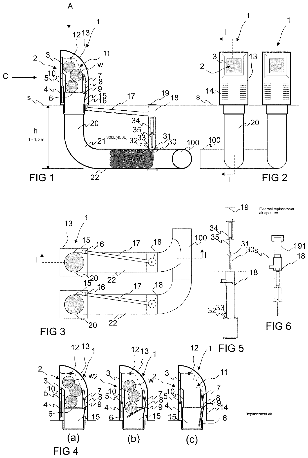
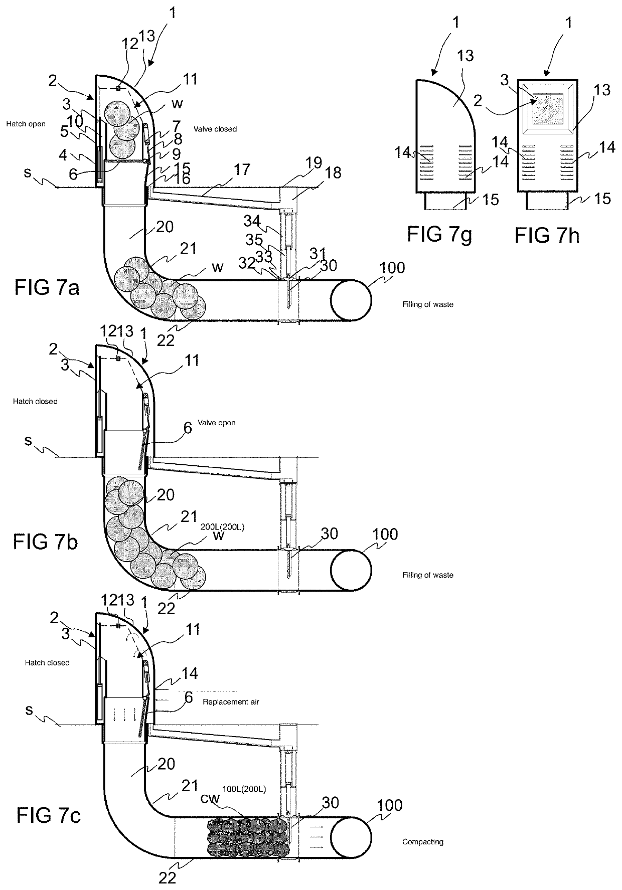
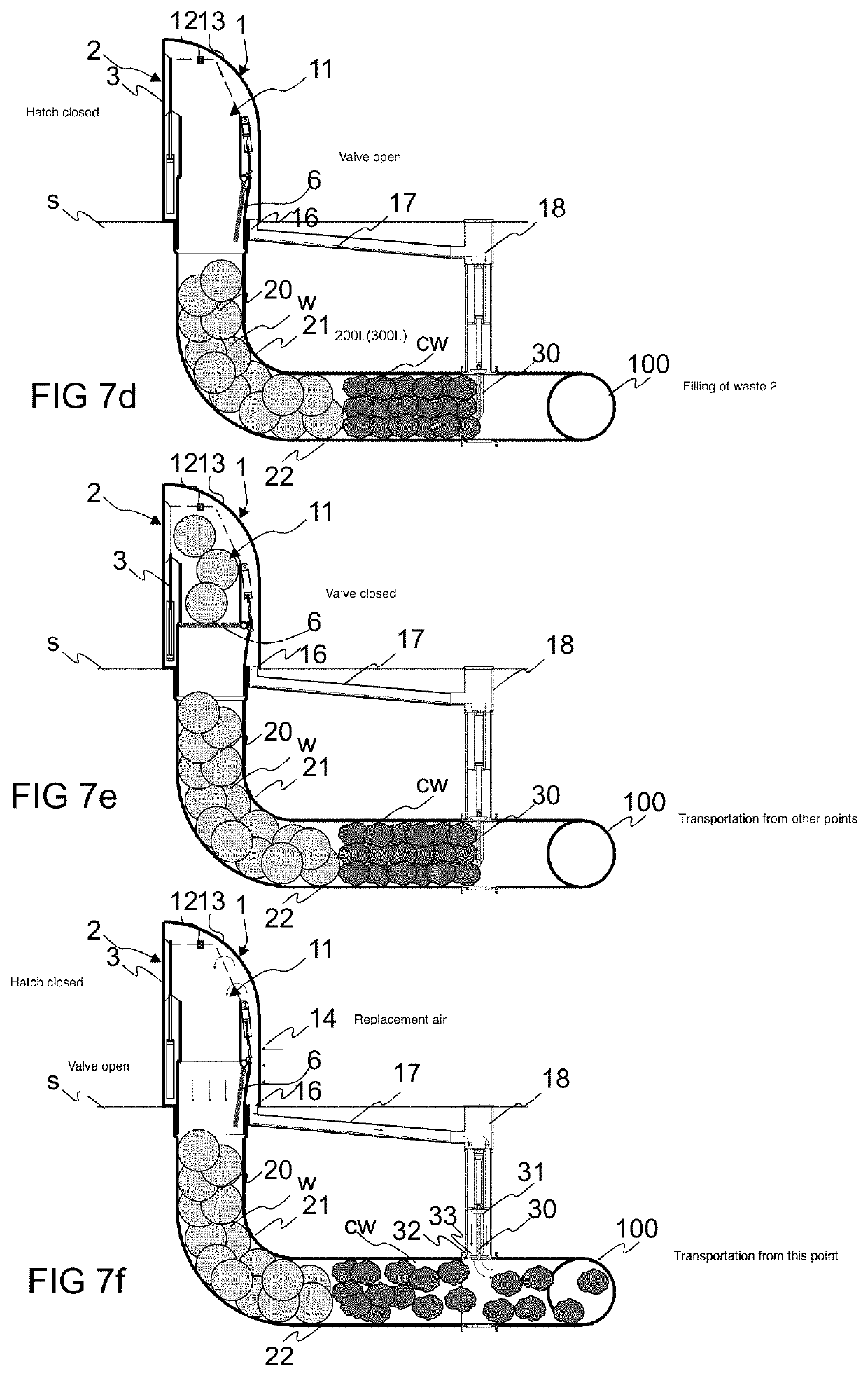
[0036]FIGS. 1, 2 and 3 present a simplified view of an apparatus according to the invention. The apparatus comprises an input point 1, which comprises an input aperture 2 for feeding material w, such as waste material or recycleable material, into a feed-in container 10 of the input point, and onwards via an intermediate container 20, 21, 22 into the material conveying pipe 100. An openable and closable hatch 3 or corresponding is in connection with the input aperture 2 in the embodiment of the figure, which hatch when closed covers the input aperture 2 and when opened enables the feeding in of material w via the input aperture into the feed-in container 10. In the embodiment of the figure an actuator 4, 5, such as a cylinder-piston combination, is arranged to drive the hatch 3 of the input aperture, to which actuator the hatch 3 is arranged movably between at least two positions, a first position, in which it covers the input aperture 2, and a second position, in which the input ap...


PUM


Abstract

Method for feeding in and for handling waste material in the channel section of a pneumatic wastes conveying system, in which method waste material or recycleable material is fed into a feed-in container from the input aperture of an input point of a pneumatic pipe transport system for material and onwards into the channel section between the feed-in container and the material conveying pipe, from where the material is conveyed along with the transporting air via the material conveying pipe to the delivery end of the pneumatic material conveying system, where the material is separated from the transporting air. In the method the material is acted upon by the combined effect of suction and replacement air in the channel section by bringing about compression in size in at least a part of the material being conveyed, by means of an impediment arranged between the conveying pipe and the material to be handled, or against the impediment, before transportation of the material to the delivery end of the pneumatic transport system for wastes.

Description

FIELD OF THE INVENTION[0001]The object of the invention is a method for feeding in and for handling material.[0002]The object of the invention is also an apparatus for feeding in and for handling waste material in the channel section of a pneumatic wastes conveying system.[0003]The invention also relates to a system for feeding in and for handling waste material in the channel section of a pneumatic wastes conveying system.BACKGROUND OF THE INVENTION[0004]The invention relates generally to material conveying systems, such as to pneumatic partial-vacuum transporting systems, more particularly to the collection and conveying of wastes, such as to the conveying of household wastes. Such systems are presented in publications WO 2009 / 080880, WO 2009 / 080881, WO 2009 / 080882, WO 2009 / 080883, WO 2009 / 080884, WO 2009 / 080885, WO 2009 / 080886, WO 2009 / 080887 and WO 2009 / 080888, among others. The invention also relates to waste feeding means, such as to input points or refuse chutes, with which w...

Claims


Application Information

Patent Timeline
Patent Type & Authority Patents(United States)
IPC IPC(8): B65G53/28E04F17/12B65G53/46B65F1/10B65F5/00
CPCE04F17/12B65F1/10B65G53/46B65F5/005B65G53/4691B65G53/4608B65G53/52B65F5/00
Inventor SUNDHOLM, GÖRAN
Owner MARICAP OY
Why Eureka
Try Eureka