Liquid crystal display device
A liquid crystal display device and substrate technology, which is applied to instruments, nonlinear optics, optics, etc., can solve the problem of magenta in the chromaticity of the screen, and achieve the effects of reducing hue shift, large opening area, and reducing time constant.
- Summary
- Abstract
- Description
- Claims
- Application Information
AI Technical Summary
Problems solved by technology
Method used
Image
Examples
Embodiment approach 1
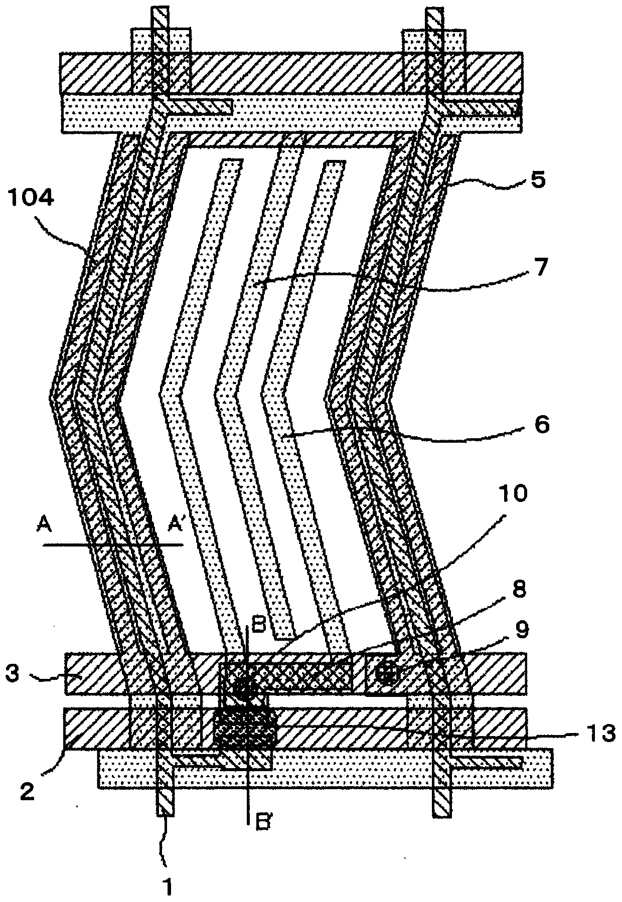
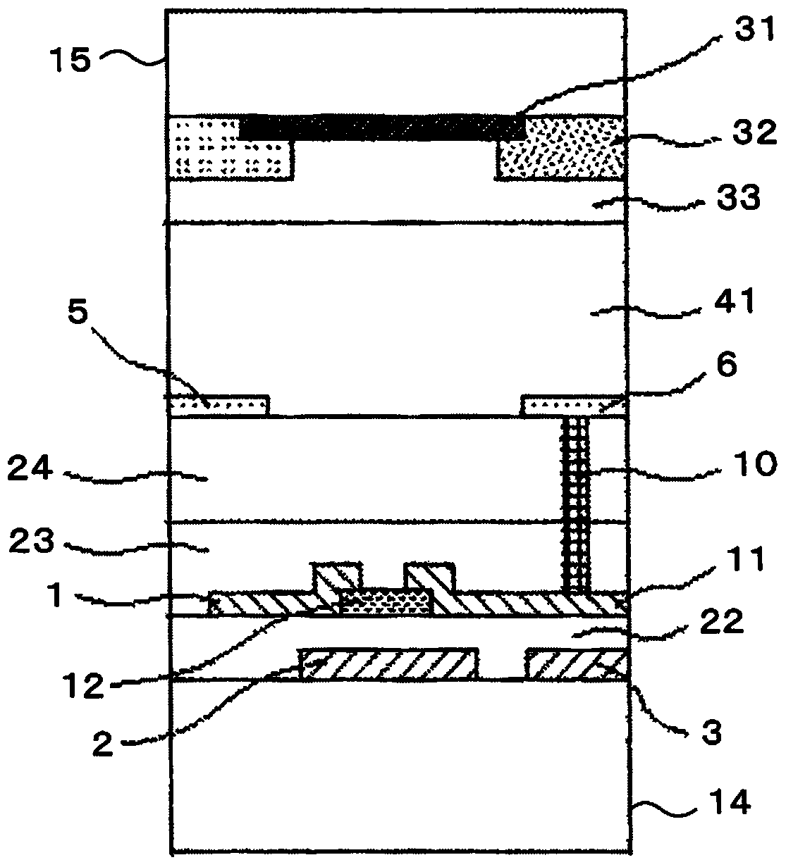
[0074] Hereinafter, the embodiments of the present invention described above will be described in more detail. will refer to Figure 7A to Figure 7C as well as Figure 8A with Figure 8B The structure of the liquid crystal display device according to Embodiment Mode 1 of the present invention will be described. Figure 7A is a top view of this embodiment, Figure 7B with Figure 7C for Figure 7A cutaway view.
[0075] The liquid crystal display device of the present embodiment includes: a transparent substrate (hereinafter referred to as "TFT substrate" (first substrate)) 14, signal wiring 1, scanning wiring 2, pixel electrode 6, counter electrode 7, and Similar elements for driving an electric field of liquid crystals are provided on a transparent substrate 14; a transparent substrate (hereinafter referred to as "color filter substrate" (second substrate)) 15, a black matrix 31, a color filter element 32 and a planarization layer 33 is provided on the transparent subs...
Embodiment approach 2
[0096] will refer to Figure 9 Embodiment 2, another embodiment of the present invention, will be described.
[0097] This embodiment is characterized in that the lower shield COM wiring 4 is provided in the extending direction of the signal wiring 1, and is also provided in the extending direction of the scanning wiring 2 in the same layer to provide a grid-shaped wiring structure. .
[0098] In the present embodiment, the signal wiring 1, the scanning wiring 2, and the lower shield COM wiring 4 are provided in layers different from each other through an insulating film, so that the corresponding layers can intersect each other in plan view, and the number of pairs of wiring can be reduced. arrangement constraints, thereby providing a grid-shaped wiring structure.
[0099] By forming the lower shield COM wiring 4 in a grid structure, the wiring resistance can be reduced, and the voltage of the lower shield COM electrode 104 can be equalized, so that highly uniform display q...
Embodiment approach 3
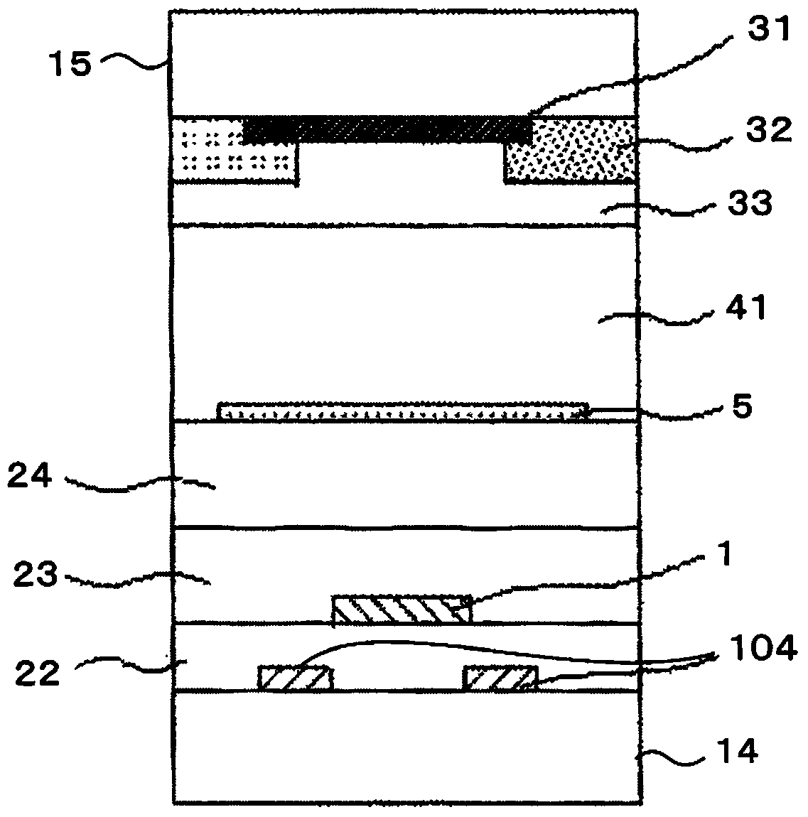
[0103] will refer to Figure 10A with Figure 10B Embodiment 3, another embodiment of the present invention, will be described. Figure 10A is a top view of this embodiment, and Figure 10B along Figure 10A A cross-sectional view taken along the line A-A'.
[0104] The present embodiment is characterized in that the lower shield COM electrode 104 is provided to overlap on the lower side of the signal wiring 1 so as to completely cover the signal wiring 1 when viewed from the normal direction of the TFT substrate 14 .
[0105] By disposing the signal wiring 1 between the upper shielding COM electrode 5 and the lower shielding COM electrode 104, the electric field generated by the signal wiring 1 can be almost completely shielded, and an image with higher display quality can be obtained.
[0106] In addition, even when a positional shift or a change in wiring width occurs during patterning of the signal wiring 1 and the lower shield COM electrode 104, the wiring pattern of ...
PUM
 Abstract
Description
Claims
Application Information
 - R&D
- Intellectual Property
- Life Sciences
- Materials
- Tech Scout
- Unparalleled Data Quality
- Higher Quality Content
- 60% Fewer Hallucinations
Browse by: Latest US Patents, China's latest patents, Technical Efficacy Thesaurus, Application Domain, Technology Topic, Popular Technical Reports.
© 2025 PatSnap. All rights reserved.Legal|Privacy policy|Modern Slavery Act Transparency Statement|Sitemap|About US| Contact US: help@patsnap.com


