System and Method for Coordinating Electronic Devices in a Wireless Communications System

a wireless communication system and wireless communication technology, applied in the field of wireless communication, can solve the problems of channel quality change, interference increase, etc., and achieve the effect of maximizing multi-user diversity, small overhead of control signaling and reference signal, and small impact on overall performance of the communications system

Active Publication Date: 2010-10-28
FUTUREWEI TECH INC
View PDF15 Cites 106 Cited by
  • Summary
  • Abstract
  • Description
  • Claims
  • Application Information

AI Technical Summary

Benefits of technology

[0011]An advantage of an embodiment is that control signaling and reference signal overhead may be very small. Therefore, their impact on the overall performance of the communications system is also very small.
[0012]A further advantage of an embodiment is that it may be possible to seamlessly and invisibly to the UE, implement a restricted scheduling technique at the NB. Therefore, the UEs may not need to modify their feedback behavior or change the nature of their feedback information.
[0013]Yet another advantage of an embodiment is that maximum multi-user diversity gains may be possible, which may significantly improve performance at light load conditions.

Problems solved by technology

It is well known that as cell size is decreased in an effort to improve spectral efficiency, interference increases.
However, one main drawback of beamforming is the so called flashlight effect where the channel quality changes between user equipment (UE) measurement and reporting, and NodeB (NB) transmission, due to the changes in the beampattern of the interfering neighbouring cells.

Method used


Image

  • System and Method for Coordinating Electronic Devices in a Wireless Communications System
  • System and Method for Coordinating Electronic Devices in a Wireless Communications System
  • System and Method for Coordinating Electronic Devices in a Wireless Communications System

Examples


second embodiment

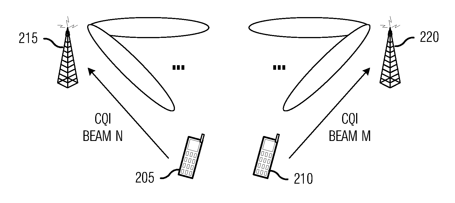
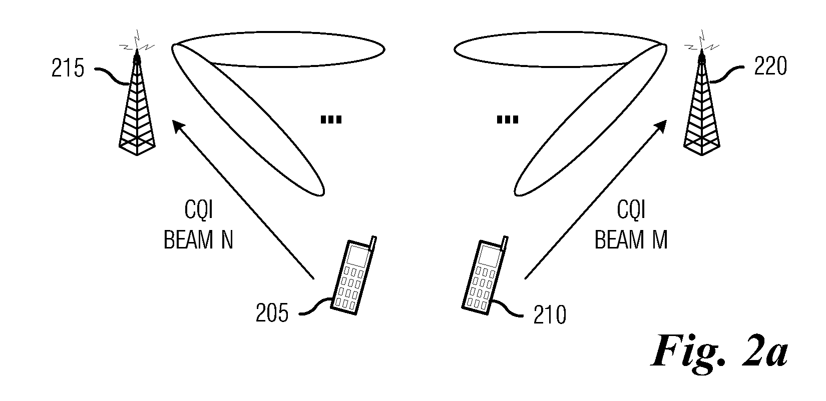
[0115]PMI CQI (All): Strict Coordinated beamforming where the NB has to adhere to the beam cycle pattern. The UE feeds back all CQI's for all subbands, delayed by 2 ms.[0116]PMI CQI (Group): Flexible Coordinated beamforming where the NB has some flexibility to trade of multi user diversity gain vs. flashlight effect, as described in [13]. The UE feeds back all CQI's for all subbands, delayed by 2 ms.

third embodiment

[0117]Cycle CQI (All CQI): Coordinated beamforming. The UE feeds back all CQI's for all subbands, delayed by 2 ms. Note the overall optimal performance.[0118]Cycle CQI (Best CQI): Coordinated beamforming The UE feeds back only the CQI's for the best beams subbands, delayed by 2 ms.

[0119]Additional performance evaluations are performed to evaluate the performance when using coordinated techniques under different traffic loads. In these evaluations, a coordinated eNB cluster as described before is again implemented. In these simulations the Reference LTE averages the reported CQI in order to limit the packet error rate. In fact if the CQI is not averaged, the performance degrades with increasing loads due to the increased flashlight effect under heavy loads. The Coordinated techniques do not need to average the CQI's since the flashlight effect is already contained. Here, one additional form of coordination was included, where the eNB has to choose between a strict coordination (Metho...


PUM


Abstract

A system and method for coordinating electronic devices in a wireless communications system are provided. A method for transmitting information by a controller includes computing a beam cycle based on transmissions from a plurality of mobile devices, receiving resource-specific channel quality indicators from the plurality of mobile devices, scheduling a transmission opportunity for a mobile device in the plurality of mobile devices, and transmitting information to the mobile device based on the scheduled transmission opportunity. The mobile devices are being served by the controller, and the scheduling is based on the beam cycle and the channel quality indicators.

Description

[0001]This application claims the benefit of U.S. Provisional Application No. 61 / 173,404, filed on Apr. 28, 2009, entitled “System and Method for Coordinating Electronic Devices in a Wireless Communications System,” and U.S. Provisional Application No. 61 / 222,000, filed on Jun. 30, 2009, entitled “Communications System with Utility Based Grouped Scheduling,” which applications are hereby incorporated herein by reference.TECHNICAL FIELD[0002]The present invention relates generally to wireless communications, and more particularly to a system and method for coordinating electronic devices in a wireless communications system.BACKGROUND[0003]During the development of Long Term Evolution (LTE), there was much discussion for the flexibility to customize LTE to maximize performance in specific environments. Also, during discussions of LTE-Advanced (LTE-A), many suggestions were made to manage interference level by using coordinated transmissions from different cells (see Ericsson, R1-08246...

Claims


Application Information

Patent Timeline
Patent Type & Authority Applications(United States)
IPC IPC(8): H04W72/12
CPCH04W72/1231H04W16/28H04W72/542
Inventor VAN RENSBURG, CORNELIUSOTERI, OGHENEKOME
Owner FUTUREWEI TECH INC
Why Eureka
Try Eureka