Lock which can be unlocked in an electrically automated manner, in particular for storage systems like lockers

An automatic unlocking and saving system technology, applied in electric locks, non-mechanical transmission-operated locks, and passenger compartment locks, etc., can solve the problems of complex control, unfavorable maintenance necessity, high cost, etc. Simple yet mechanically compact effect

Active Publication Date: 2010-08-11
KEBA HANDOVER AUTOMATION GMBH
View PDF2 Cites 13 Cited by
  • Summary
  • Abstract
  • Description
  • Claims
  • Application Information

AI Technical Summary

Problems solved by technology

However, the transmission is likewise a weak point with regard to breakage under high shock loads and is also disadvantageou

Method used


Image

  • Lock which can be unlocked in an electrically automated manner, in particular for storage systems like lockers
  • Lock which can be unlocked in an electrically automated manner, in particular for storage systems like lockers
  • Lock which can be unlocked in an electrically automated manner, in particular for storage systems like lockers

Examples


Embodiment Construction

[0040] First of all, it should be noted that in the different described embodiments the same parts are provided with the same reference signs or the same component signs, wherein the disclosure content contained in the entire description can be referred to with the same reference signs or the same on the same part of the member mark. Positional indications selected in the description, such as top, bottom, side, etc., relate to the directly described and illustrated figure and can be transferred to a new position in the event of a position change. Furthermore, individual properties or combinations of features in the different exemplary embodiments shown and described can also form independent, inventive or inventive solutions in themselves.

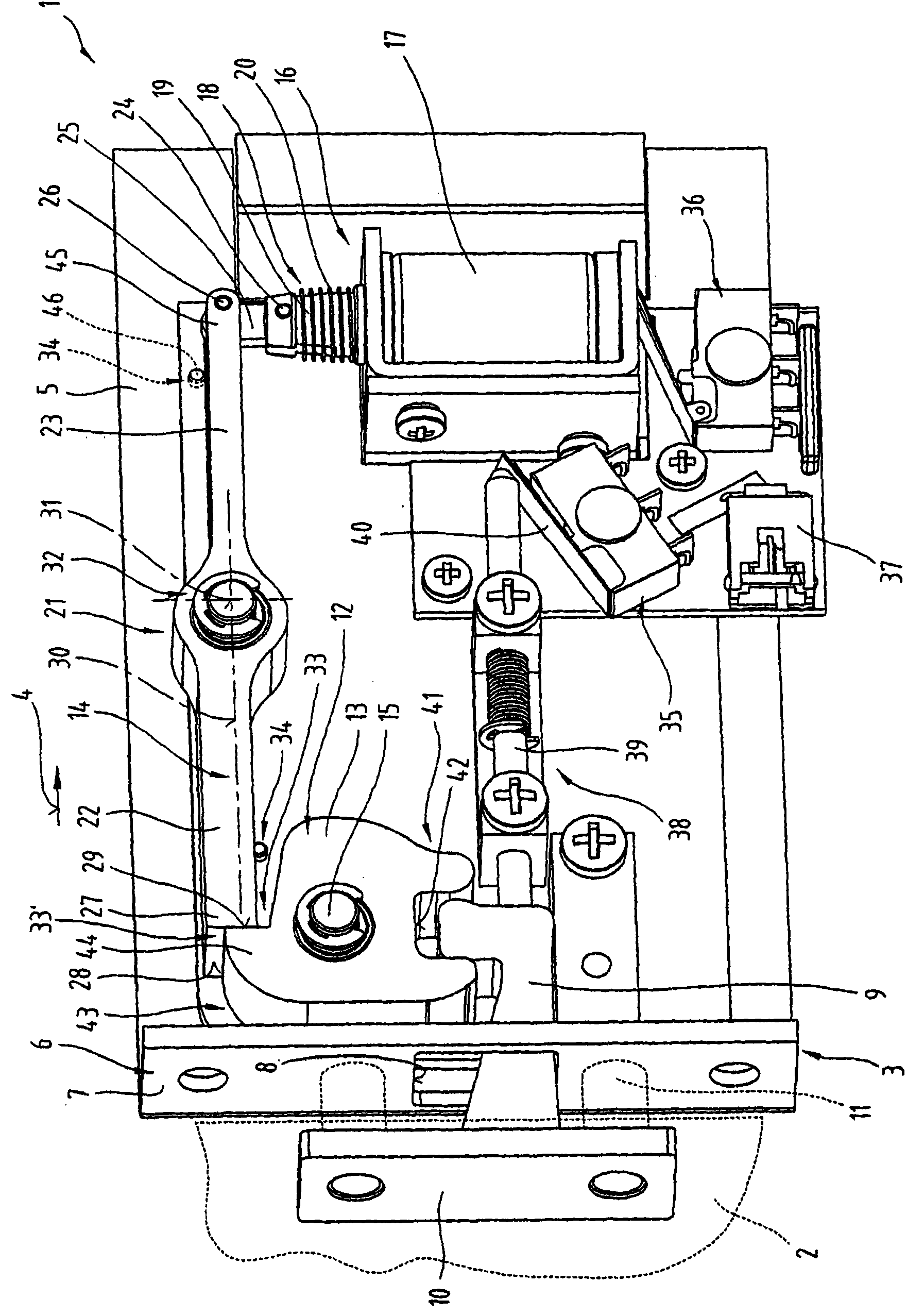
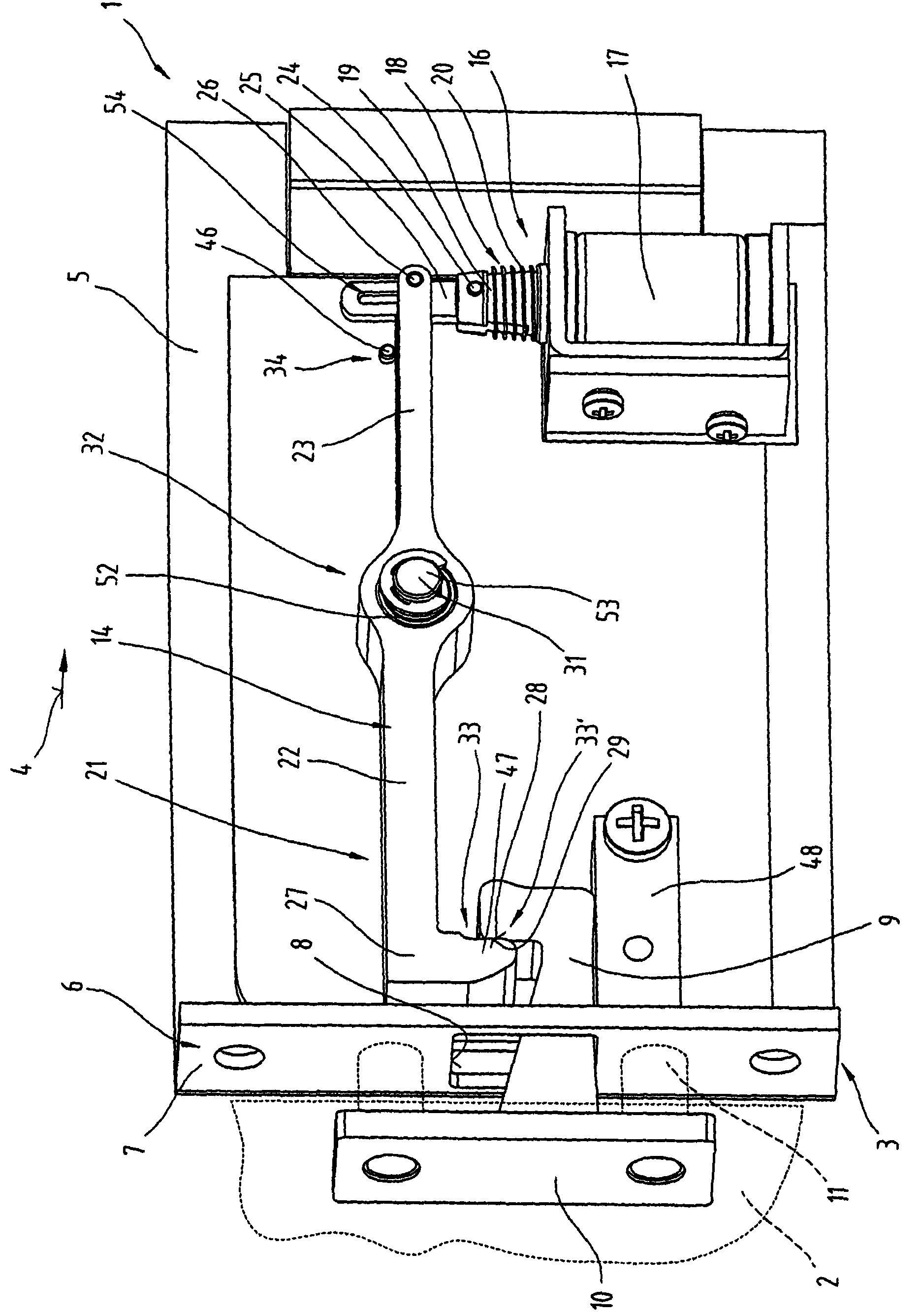
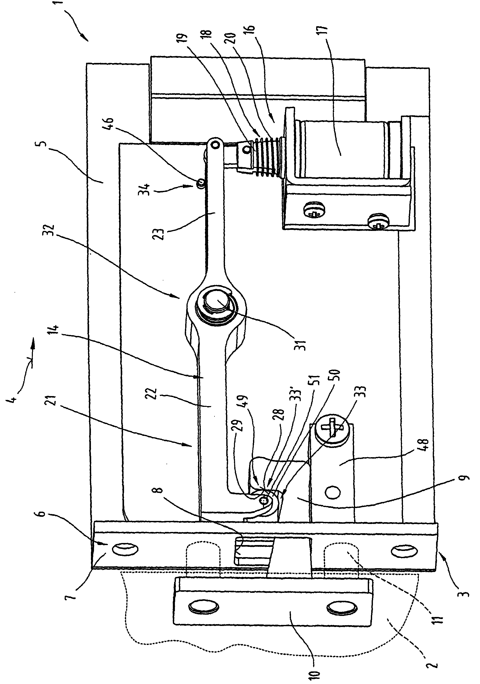
[0041] figure 1 with 2 A perspective view of the lock 1 embodied according to the invention is shown in each case with the side element or the cover element removed. The lock 1 is mainly suitable for automatic storage devices, in partic...


PUM


Abstract

The invention relates to a lock (1) which can be unlocked in an electrically automated manner, in particular for use for storage systems like lockers. In this case, a blocking element (9) is provided which can be inserted into the lock (1), can be blocked in the lock (1) and in this case holds a locker door (2), which is firmly connected to the blocking element (9), in the closed position. Furthermore, a blocking catch (14) is provided which can be moved rotationally in a limited manner and which, on assuming its blocking position, engages either directly or indirectly via at least one coupling element (12), which is mounted such that it can move, with the blocking element (9). The essential feature in this case is that the section of a force introduction point (33') for the blocking force into the blocking catch (14) is designed such that force and impulse introduction, which are dependent on an interlock on the installation, from the blocking element (9) or from an intermediate coupling element (12), which may be provided, to the blocking catch (14) occurs directed virtually exclusively radially with respect to the pivoting axis (31) thereof, and any tangential force or impulse components which may occur can be transmitted virtually exclusively by friction forces to the force introduction point (33'). This achieves increased security against external manipulatory actions.

Description

technical field [0001] The invention relates to a lock capable of being automatically unlocked electrically, as stated in the preamble of claim 1 . Background technique [0002] An electrically unlockable or opening lock, in particular for automated safe installations or the like, is known from DE 92 09 053 U1. A rotary bolt provided in the lock housing for a locking hook fixedly connected to a door panel is biased by means of a spring so that when the rotary bolt is released or opened it is converted into a rotary movement in the opening or release direction. The disk-shaped swivel bolt has a respective groove on two directly adjoining peripheral parts, wherein the first groove is formed for the engagement of the locking hook and the second groove is provided for positive locking with a linearly displaceable pin. Embedded, the latch consists of an armature of an electromagnet. When the armature of the electromagnet engages in the swivel bolt, the swivel bolt is locked in ...

Claims


Application Information

Patent Timeline
IPC IPC(8): E05B47/06E05B65/12E05B65/20
CPCE05B47/0696E05B47/0004E05B77/24E05B47/0607E05B2047/0069E05B81/08E05B47/023E05B2047/0093Y10T70/7062Y10T70/5097Y10T292/1082Y10T70/65
Inventor H-P·温特施泰格
Owner KEBA HANDOVER AUTOMATION GMBH
Why Eureka
Try Eureka