Lifting hook structure optimization method

An optimization method and hook technology, applied in electrical digital data processing, instruments, geometric CAD, etc., can solve problems such as not easy to ensure the hook pulley block

Active Publication Date: 2020-01-10
XCMG CONSTR MACHINERY
View PDF4 Cites 0 Cited by
  • Summary
  • Abstract
  • Description
  • Claims
  • Application Information

AI Technical Summary

Problems solved by technology

But even so, because the hook is working, the hook pulley block will have a certain inclination, it is not easy to ensure that the inclination angle of the hook pulley block is always controlled within the allowable range

Method used


Image

  • Lifting hook structure optimization method
  • Lifting hook structure optimization method
  • Lifting hook structure optimization method

Examples


Embodiment Construction

[0059] Various exemplary embodiments of the present disclosure will now be described in detail with reference to the accompanying drawings. The description of the exemplary embodiments is illustrative only, and in no way restricts the disclosure, its application or uses. The present disclosure can be implemented in many different forms and is not limited to the embodiments described here. Rather, these embodiments are provided so that this disclosure will be thorough and complete, and will fully convey the scope of the disclosure to those skilled in the art. It should be noted that relative arrangements of parts and steps, compositions of materials, numerical expressions and numerical values ​​set forth in these embodiments should be interpreted as illustrative only and not as limiting, unless specifically stated otherwise.

[0060] "First", "second" and similar words used in the present disclosure do not indicate any order, quantity or importance, but are only used to distin...


PUM


Abstract

The invention relates to a lifting hook structure optimization method, comprising the steps: obtaining tension borne by all strands of steel wire ropes wound around a lifting hook pulley block in a no-load state; obtaining the distance between each strand of steel wire rope and a set reference point when the lifting hook pulley block inclines at an allowable inclination angle; calculating the total moment of the tension; calculating the distance between the gravity center of the lifting hook and a set reference point when the axis of the lifting hook pulley block inclines at an allowable inclination angle according to the total moment and the weight of the lifting hook; calculating the calculated value of the vertical distance between the gravity center of the lifting hook and the axis ofthe lifting hook pulley block according to the horizontal distance between the gravity center of the lifting hook and the set reference point when the axis of the lifting hook pulley block is horizontal and inclines by an allowable inclination angle; and optimizing the structure of the lifting hook according to the calculated value to adjust the actual value of the vertical distance between the gravity center of the lifting hook and the axis of the lifting hook pulley block. According to the embodiment of the invention, the inclination angle of the optimized lifting hook pulley block can be controlled within an allowable range as much as possible.

Description

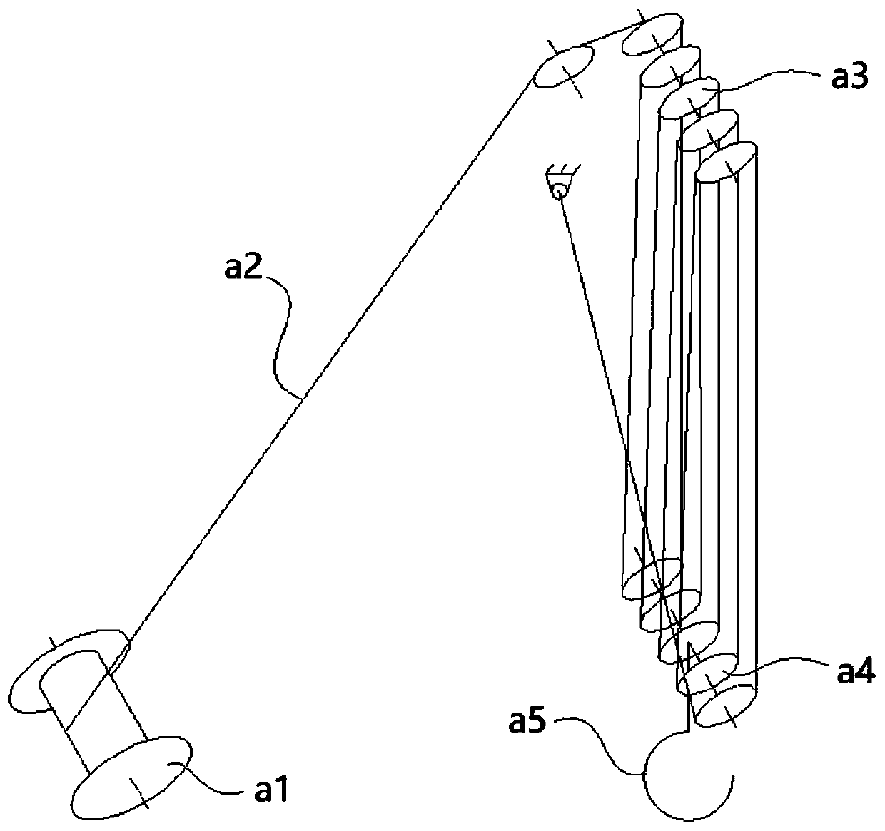
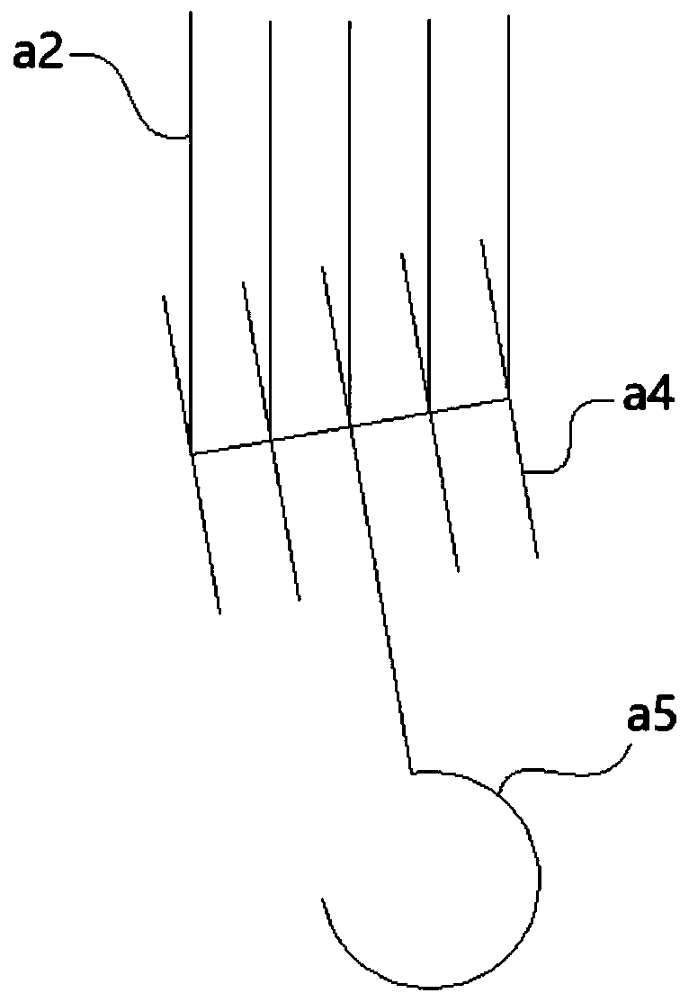
technical field [0001] The present disclosure relates to the field of engineering design, in particular to a method for optimizing a hook structure. Background technique [0002] A crane is a machine used to lift and move heavy objects. The lifting system of a crane usually includes a boom, a hook, a hoist, a boom pulley block, and a wire rope. The boom is a part of the crane that is located between the main engine and the hook to support the load. The winch is a mechanism on the crane used to wind the wire rope and provide pulling force for the hook through the wire rope. The hook is a device used to hook and lift heavy objects on the crane, including the hook head, hook pulley block, etc. [0003] Such as figure 1 Shown is a schematic diagram of the principle of the hoisting system of the crane in the related art. exist figure 1 , the winch a1 is wound with a wire rope a2, and the wire rope a2 is wound between the arm pulley block a3 and the hook pulley block a4 in t...

Claims


Application Information

Patent Timeline
Patent Type & Authority Applications(China)
IPC IPC(8): G06F30/17G06F119/14
Inventor 孙影郝敏李为民赵江平赵波
Owner XCMG CONSTR MACHINERY
Why Eureka
Try Eureka