Oscillator circuit and oscillator

a technology of oscillator and oscillator, which is applied in the direction of oscillator stabilization, oscillator generator, electrical apparatus, etc., can solve the problems of power voltage loss vcc, oscillator frequency change, output level drop,

Inactive Publication Date: 2006-07-11
NIHON DEMPA KOGYO CO LTD
View PDF11 Cites 11 Cited by
  • Summary
  • Abstract
  • Description
  • Claims
  • Application Information

AI Technical Summary

Benefits of technology

[0017]The present invention was made in the light of the problems involved with this conventional oscillator circuit, with the objective of providing a crystal...

Problems solved by technology

However, this conventional crystal oscillator circuit has a problem in that the oscillation frequency changes with variations in the power voltage Vcc.
However, the stabilizing circuit in such a case causes losses in the power voltage Vcc.
Thus, a problem arises in that the output level drops, particularly when the circuit is driven at a low voltage such as below 3.3 V.
However, excessive DC current in the pull-down resistor 9a could lead to ...

Method used


Image

  • Oscillator circuit and oscillator
  • Oscillator circuit and oscillator
  • Oscillator circuit and oscillator

Examples


first embodiment

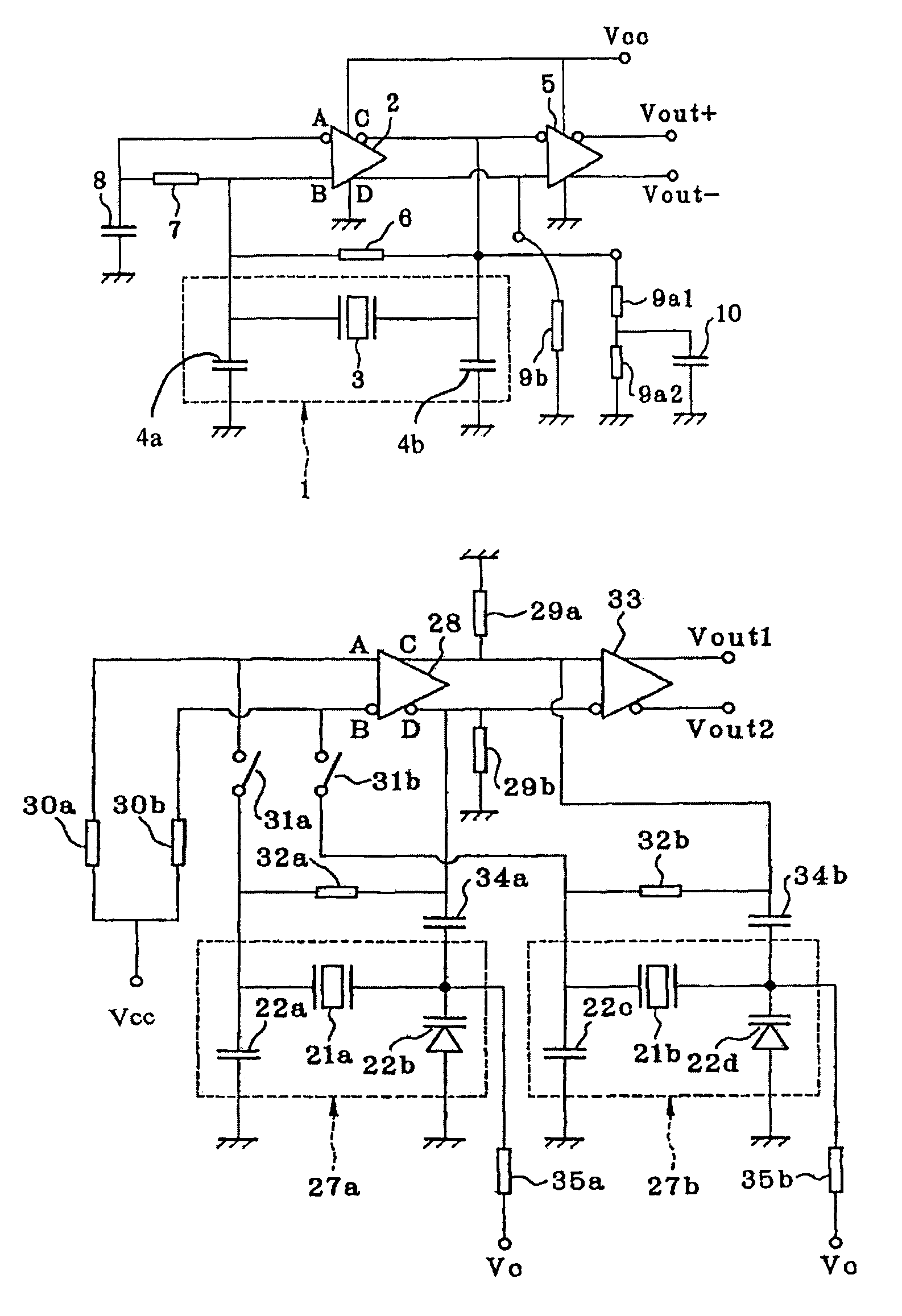
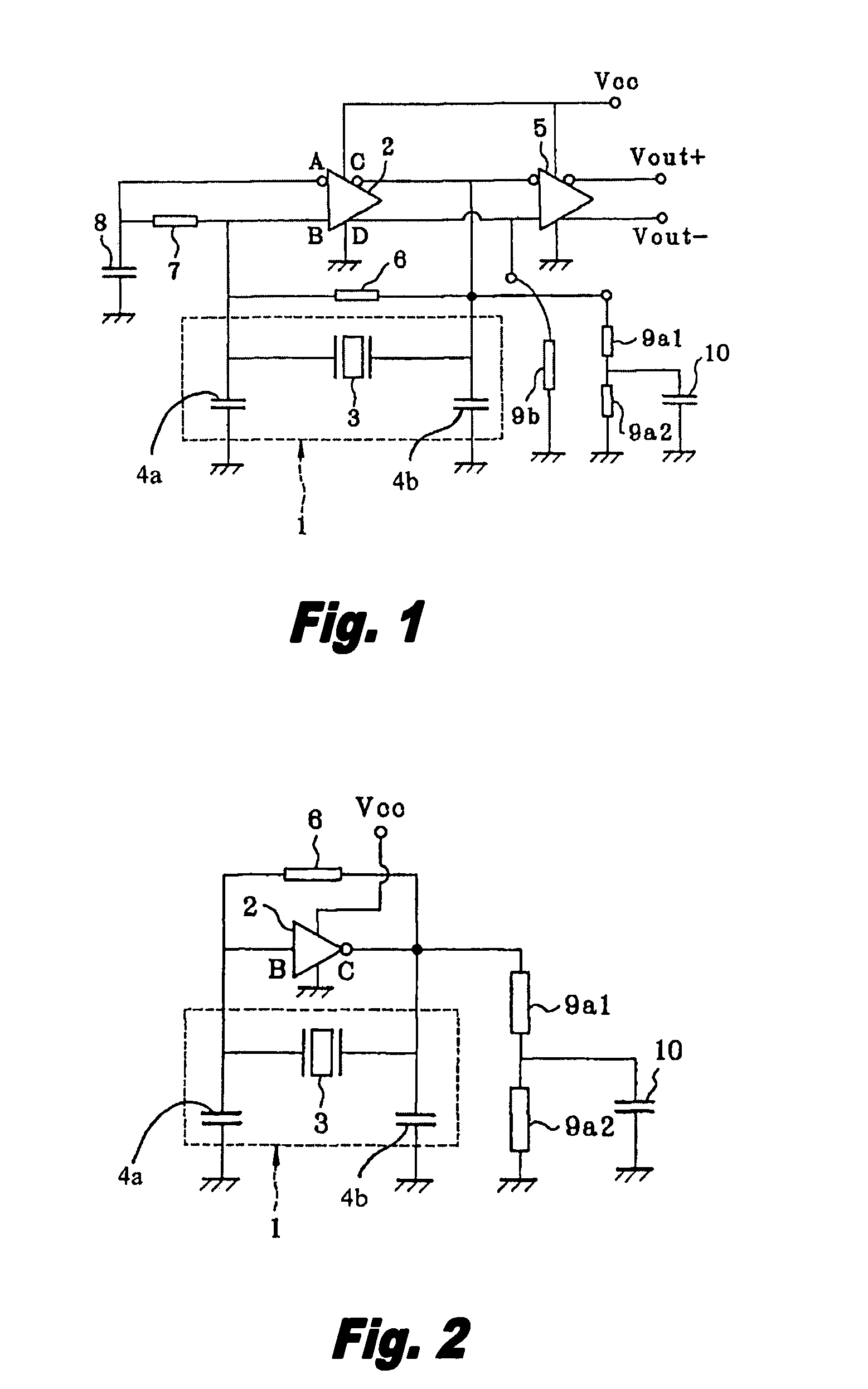
[0036]A first embodiment of a crystal oscillator circuit in accordance with the present invention is shown in FIGS. 1 to 3 with FIG. 1 showing the crystal oscillator circuit, FIG. 2 showing a simplified oscillator circuit, and FIG. 3 showing an internal circuit diagram of the ECL circuitry.

[0037]The crystal oscillator circuit of the present invention is configured of a resonance circuit 1 and an oscillation amplifier 2, as shown within the dotted line in FIG. 1. The resonance circuit 1 is formed of a crystal oscillator 3 and dividing capacitors 4a and 4b, where the crystal oscillator 3 is of AT cut or the like and functions as an inductor component. The dividing capacitors 4a and 4b are connected to the two ends of the crystal oscillator 3 and each is connected to ground.

[0038]The oscillation amplifier 2 has the abovementioned emitter coupled logic (ECL) structure, where the ECL circuit integrates a differential amplifier having two inputs A and B and two outputs C and D, of mutuall...

second embodiment

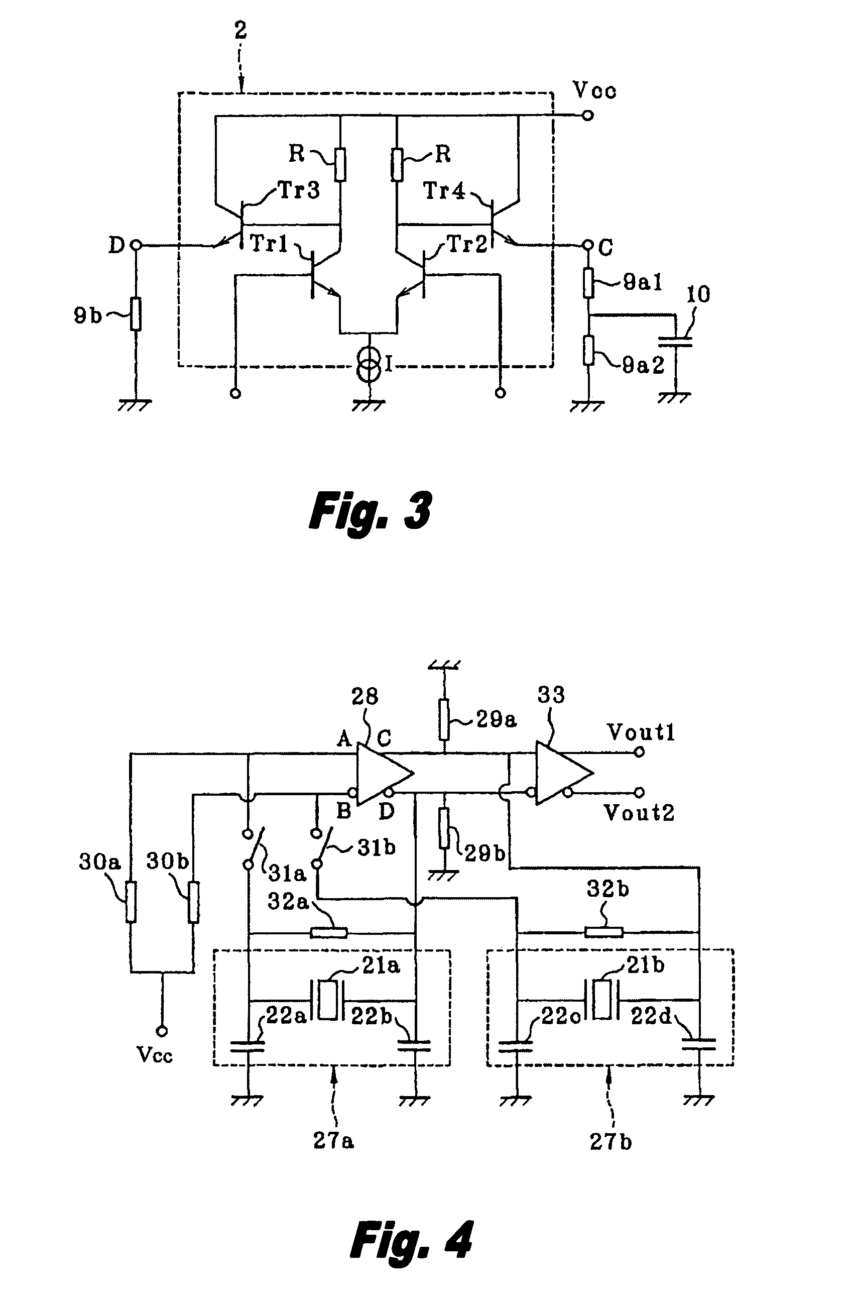
[0045]A circuit diagram that illustrates an embodiment of the frequency-switching oscillator in accordance with the present invention is shown in FIG. 4.

[0046]The frequency-switching oscillator of this invention is configured of an oscillation amplifier 28 of ECL structure (formed of an oscillation ECL circuit) that has a first resonance circuit 27a comprising a quartz crystal oscillator 21a and dividing capacitors 22a and 22b, and a second resonance circuit 27b comprising a crystal oscillator 21b and dividing capacitors 22c and 22d. The oscillation ECL circuit 28 incorporates a differential amplifier and has two input terminals A and B and two output terminals C and D, of mutually opposite phases.

[0047]With the frequency-switching oscillator of the present invention, the emitters of a first transistor Tr1 and a second transistor Tr2 are connected in common and are grounded through a constant-current source I, as shown in FIG. 5. The configuration is such that the collectors of the ...


PUM


Abstract

The present invention relates to a crystal oscillator circuit in which the output level is maintained to prevent changes in oscillation frequency due to variations in power voltage. This crystal oscillator circuit comprises a resonance circuit formed of a crystal oscillator (which acts as an inductor component) and dividing capacitors, an oscillation amplifier formed of ECL circuitry driven by a power voltage connected to the resonance circuit, and a pull-down resistor between an output terminal of the ECL circuit and ground. The pull-down resistor acts as serially-connected dividing resistors and also a bias capacitor is provided between a connection point between those dividing resistors and ground. The present invention also relates to a frequency-switching oscillator having a simple circuit design and a small number of components. This frequency-switching oscillator enables a configuration in which an oscillation amplifier that is a two input, two output type of ECL circuit having mutually inverted signals is connected to a resonance circuit formed of a crystal oscillator and dividing capacitors; a first resonance circuit provided with a first electronic switch is connected between one pair of input-output terminals for mutually inverted signals of the ECL circuit; a second resonance circuit is connected between another pair of input-output terminals for mutually inverted signals of the ECL circuit; and the resonance frequencies of the first and second resonance circuits are different and also the first and second electronic switches are switched to select one of the resonance circuits.

Description

BACKGROUND OF THE INVENTION[0001]The present invention relates to an oscillator circuit for high frequencies and, in particular, to a crystal oscillator circuit in which changes in the oscillation frequency due to variations in the power voltage are prevented.[0002]Crystal oscillator circuits usually have highly stable frequencies, so they are applied as frequency sources in different types of electronic appliances. There have recently been requests for a crystal oscillator circuit with a high oscillation frequency, for building optical communications systems. One of these utilizes an emitter coupled logic (ECL) circuit that operates at high speed, as an oscillation amplifier. A conventional type of crystal oscillator circuit is shown in FIGS. 7 to 9, with FIG. 7 showing the crystal oscillator circuit, FIG. 8 showing the internal ECL circuitry, and FIG. 9 showing a simplified oscillator circuit.[0003]This conventional oscillator circuit is configured of a resonance circuit 1 and an ...

Claims


Application Information

Patent Timeline
IPC IPC(8): H03B5/32H03B5/12H03B5/30H03B5/36H03L1/00
CPCH03B5/32H03B5/368H03B5/36
Inventor HASHIMOTO, HIDEO
Owner NIHON DEMPA KOGYO CO LTD
Why Eureka
Try Eureka