
Index tab, index tab bearing sheet and method of using an index tab

a technology of index tabs and bearing sheets, applied in the field of index tabs, can solve the problems of affecting the use of index tabs, difficulty in aligning, adhering to the tabs to divider sheets or other tab-bearing media, etc., and achieves the effect of accurately aligning the tabs, easy positioning, and easy alignmen

Inactive Publication Date: 2008-12-23
CCL LABEL INC
View PDF29 Cites 11 Cited by
  • Summary
  • Abstract
  • Description
  • Claims
  • Application Information

AI Technical Summary

Benefits of technology

The index tab ensures easy and secure alignment and attachment to mounting sheets with reduced user intervention, maintaining alignment and securing tabs of varying thicknesses effectively.

Problems solved by technology

A number of problems are associated with the use of such tabs.
These problems include difficulties with alignment and with adhering the tabs to divider sheets or other tab-bearing media.
There are several problems inherent to the tab design.
For example, the projecting bead may become crushed or otherwise lose its rigidity and form if the two sides of the tab are pressed together.
The other side of the index tab is left free, such that it cannot be easily aligned with the mounting sheet or with the other, mounted, side of the index tab.
Therefore, the index tab may be unevenly mounted upon the mounting sheet.
Thus, the alignment means is actually removed as the adhesive is exposed, such that when the tab is applied it may no longer be aligned with the mounting sheet at all.
Unfortunately, many of the shoulder constructions cause the tab portion of the index tab to lie outside of the plane of the mounting sheet.
This need to carefully control the separation of the tab extensions during the mounting procedure makes the procedure cumbersome.

Method used


Image

  • Index tab, index tab bearing sheet and method of using an index tab
  • Index tab, index tab bearing sheet and method of using an index tab
  • Index tab, index tab bearing sheet and method of using an index tab

Examples


exemplary embodiment 301

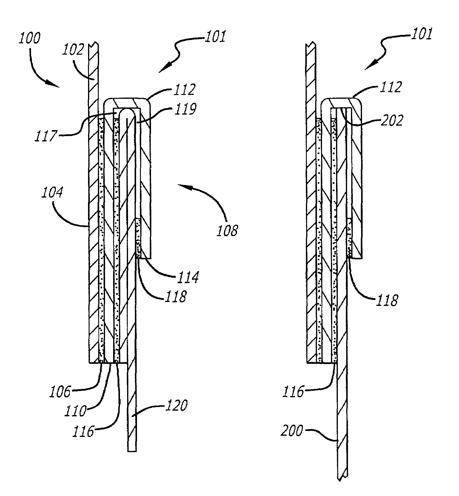
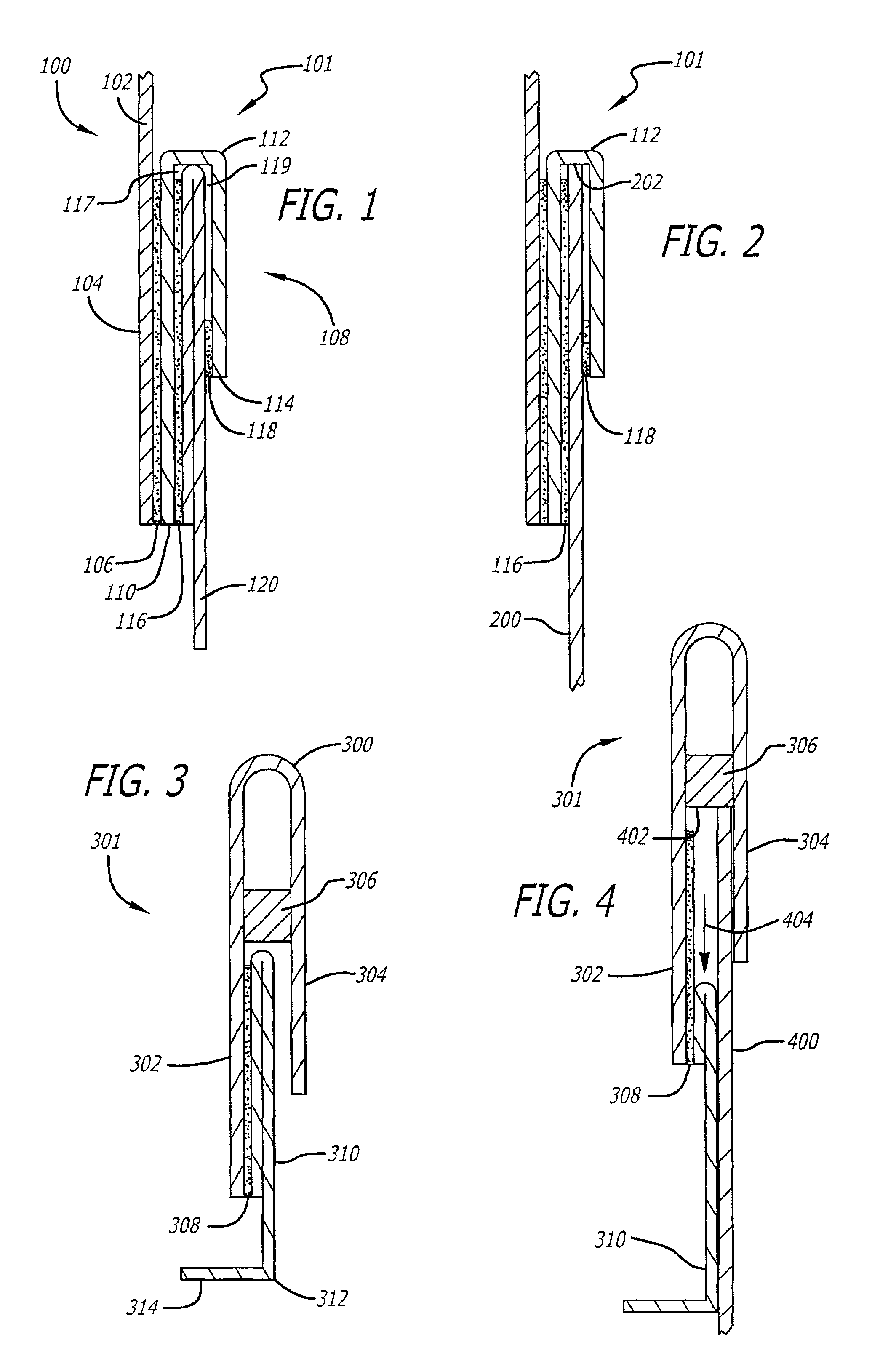
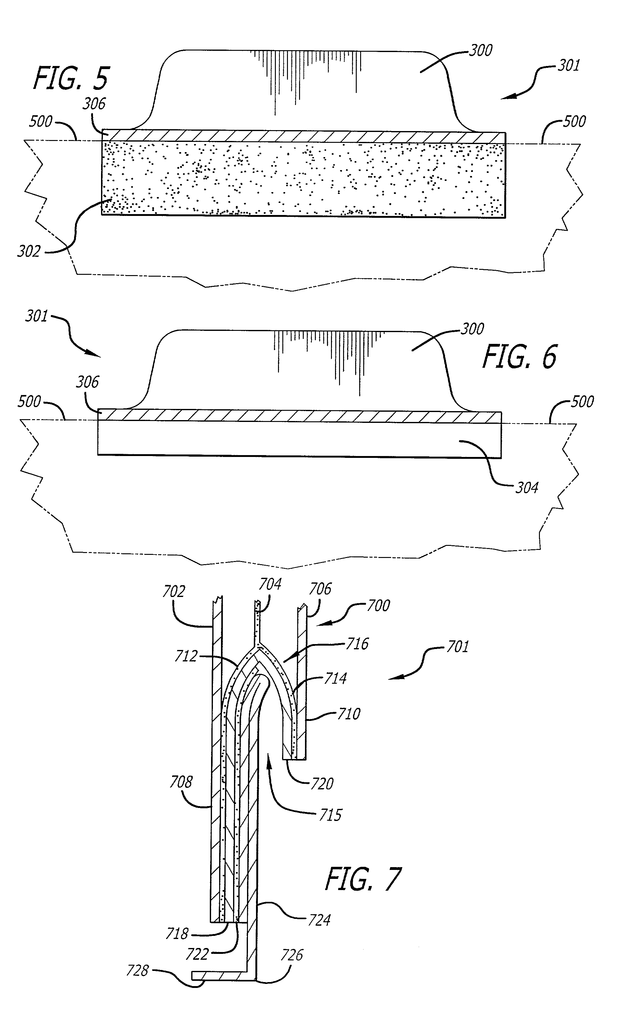
[0061]The second exemplary embodiment 301 of the present invention as it is applied to a mounting sheet 400 is depicted in FIG. 4. Lower edge 402 of heat fuse 306 is aligned with an edge of mounting sheet 400 prior to application. Then, releasable backing 310 is pulled downward, as indicated at arrow 404, to expose adhesive layer 308. Tab extension 302 and hinge 304 are then pressed together to engage adhesive layer 308 with divider sheet 400, securing the tab in place.

[0062]FIGS. 5 and 6 illustrate front and rear views, respectively, of an exemplary index tab according to the present invention. An edge 500 of a mounting sheet is aligned with the tab at heat fuse stopper 306. Tab portion 300 extends above mounting sheet edge 500. In the front view, tab extension 302 extends below mounting sheet edge 500 and is adhered to the mounting sheet by the underlying adhesive layer. In the rear view, tab hinge 304 also extends below mounting sheet edge 500, though not as far as the length of ...

exemplary embodiment 701

[0063]A third exemplary embodiment 701 of the present invention is illustrated in FIG. 7. In this cross-sectional view, it can be seen that tab portion 700 comprises three layers of material; namely, a first outside tab portion 702 comprised of suitable tab material such as card stock or plastic, an internal layer of adhesive 704, and a second outside tab portion 706 also comprised of card stock or plastic. Internal adhesive layer 704 binds the two outside tab portions 702 and 706 together. The piece of material which forms first outside tab portion 702 extends downward to form tab extension 708. Likewise, the piece of material which forms outside tab portion 706 extends downward to form tab hinge 710. A pocket, shown generally at 715, is then formed and adhered to the inside surfaces of tab extension 708 and tab hinge 710 with adhesive layers 712 and 714, respectively. The pocket 715 comprises a single piece of material, such as a strip of paper for example, folded to form stopper ...

exemplary embodiment 801

[0064]FIG. 8 illustrates a fourth exemplary embodiment 801 of the invention. In this embodiment, tab portion 800 comprises a first tab portion layer 802 and a second tab portion layer 804, connected by an adhesive layer 806. Lower edge of adhesive layer 806 acts as a stopper for aligning the tab with an edge of a mounting sheet as in the previously described embodiments. In this embodiment, a mounting sheet may be inserted between releasable backing 808 and tab hinge 810. Then releasable backing 808 is grasped at easily grippable tab 812 and pulled downward as indicated by arrow 814 to expose adhesive layer 816 which will adhere to the surface of the mounting sheet. Once the tab is mounted upon the mounting sheet, the tab is aligned, via adhesive stopper 806, with the top edge of the mounting sheet. An additional feature that can be incorporated into the fourth exemplary embodiment is a second layer of adhesive on the inside surface of hinge 810. This second layer of adhesive would ...


PUM


Abstract

Index tabs having a mechanism for alignment with an edge of a mounting sheet, and methods for making and using the same. Embodiments exemplary of the alignment mechanism include various stopper constructions, pocket constructions, and the like. For example, a pocket can be formed within an index tab, such that the pocket contains an opening at the bottom for receiving an edge of a mounting sheet. The edge of the mounting sheet becomes aligned with the index tab when it fully engages the top of the pocket, which acts as a stopper. After alignment is achieved, the index tab is adhered to the mounting sheet. Various shapes and materials that are beneficial in the new tab constructions are also disclosed.

Description

CROSS REFERENCE TO RELATED APPLICATION[0001]This application claims the benefit of U.S. Provisional Patent Application No. 60 / 277,141, which was filed on Mar. 19, 2001 and is entitled “Stopper Aligning Tab Construction for Divider Sheets and the Like.”BACKGROUND OF THE INVENTION[0002]1. Field of the Invention[0003]The present invention relates to improvements in index tabs for use on divider sheets, filing cards and the like. More particularly, the present invention relates to index tabs that are easy to align along the edge of a divider sheet and easy to affix thereto.[0004]2. General Background and State of the Art[0005]Index tabs comprising a piece of material folded over upon itself to form a double ply tab having adhesive on its inside edges have been used extensively in the past. A number of problems are associated with the use of such tabs. These problems include difficulties with alignment and with adhering the tabs to divider sheets or other tab-bearing media.[0006]A prior ...

Claims


Application Information

Patent Timeline
Patent Type & Authority Patents(United States)
IPC IPC(8): G09F23/10B42F21/00B42F21/04
CPCB42F21/00B42F21/04
Inventor SATO, JAY K.YAMAMOTO, NORMAN
Owner CCL LABEL INC
Learn More