Top of Rail Foam Bar

a foam bar and rail technology, applied in rail lubrication, rail wetting/lubrication, rails, etc., can solve the problems of substantial waste of friction modifying material and inability to reach the modifying material

Active Publication Date: 2010-12-02
L B FOSTER RAIL TECH INC
View PDF58 Cites 21 Cited by
  • Summary
  • Abstract
  • Description
  • Claims
  • Application Information

AI Technical Summary

Benefits of technology

[0008]In a further embodiment, a rail applicator includes a foam body configured to apply friction modifying material to a surface of a rail. The foam body defines a flow passageway that extends through the foam body for friction modifying material to flow through. The applicator also includes an applicator support with the foam body being secured to the applicator support.
[0009]In another embodiment, a method of applying friction modifying material to a rail includes engaging a head portion of a rail with an applicator. The applicator includ

Problems solved by technology

Oftentimes, the friction modifying material does not reach the center of the rail or substantial amounts of

Method used


Image

  • Top of Rail Foam Bar
  • Top of Rail Foam Bar
  • Top of Rail Foam Bar

Examples


Embodiment Construction

[0034]For purposes of the description hereinafter, spatial orientation terms, if used, shall relate to the referenced embodiment as it is oriented in the accompanying drawing figures or otherwise described in the following detailed description. However, it is to be understood that the embodiments described hereinafter may assume many alternative variations and embodiments. It is also to be understood that the specific devices illustrated in the accompanying drawing figures and described herein are simply exemplary and should not be considered as limiting.

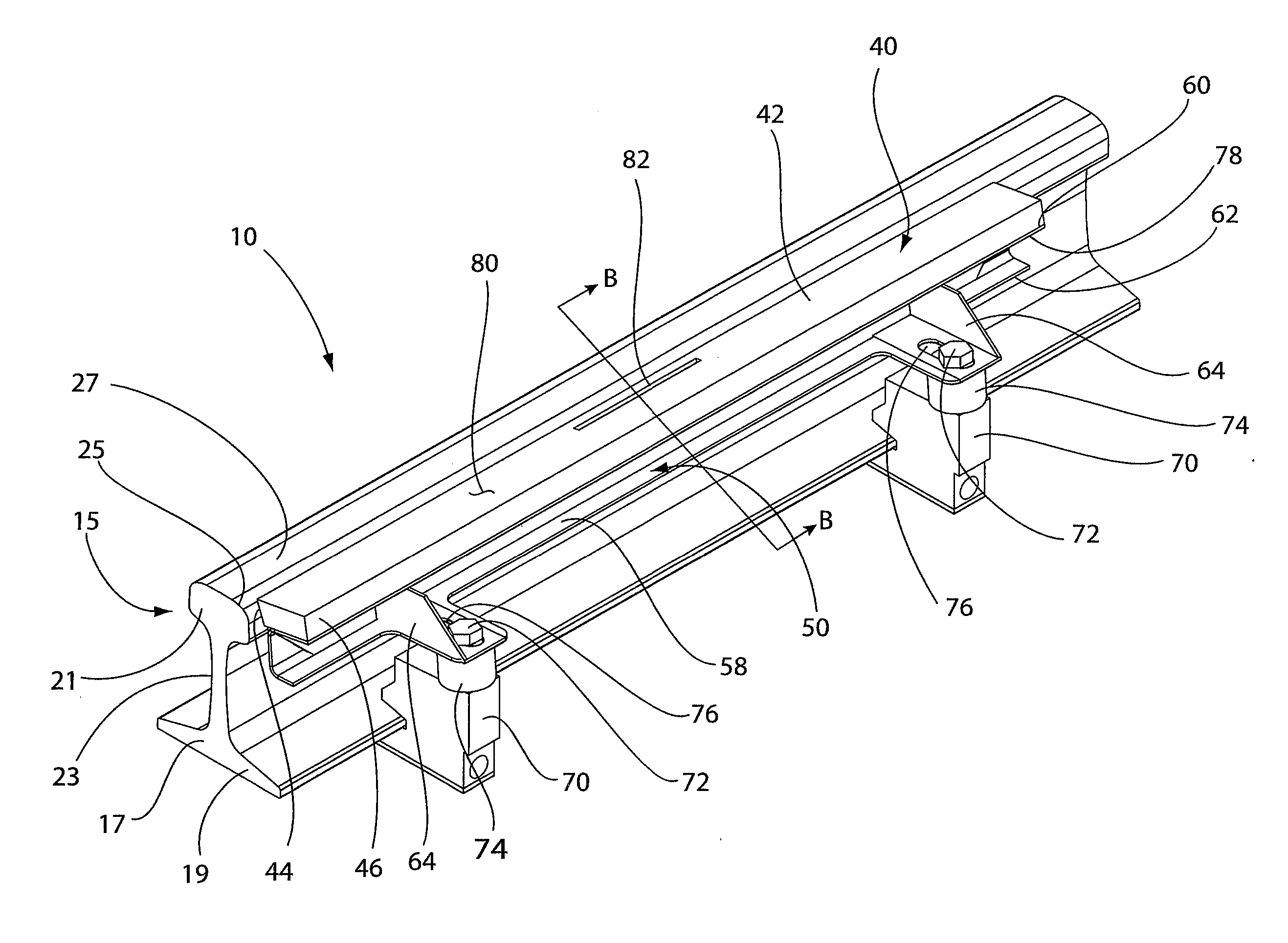
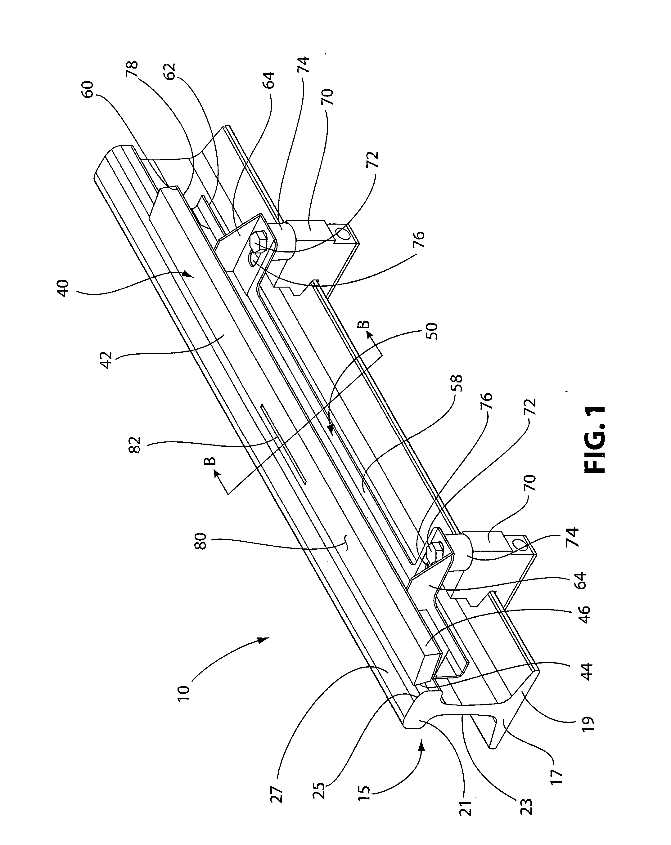
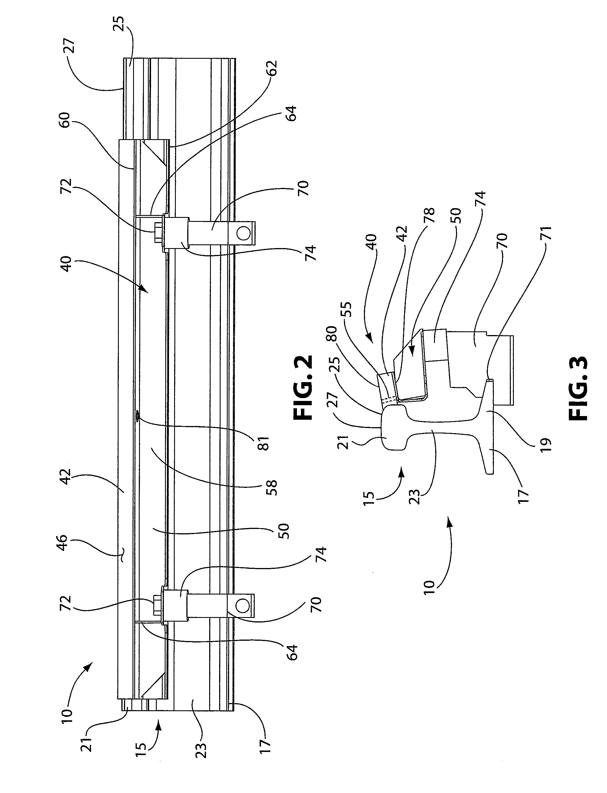
[0035]Referring to FIGS. 1-3, one embodiment of a rail applicator assembly 10 is shown. The rail applicator assembly 10 includes a railroad rail 15 and an applicator 40 for applying a friction modifying material to the rail 15. The rail 15 includes a base portion 17 with flanges 19 extending therefrom and a head portion 21 having a web portion 23, which extends between the head portion 21 and the base portion 17. The head portion 21...


PUM


Abstract

A rail applicator assembly includes a rail having a head portion, a base portion, and a web portion extending between the head portion and the base portion. The head portion defines an outer surface. An applicator for applying a friction modifying material to the surface of the rail includes a foam body and an applicator support. The foam body is secured to the applicator support and defines a flow passageway that extends through the foam body for friction modifying material to flow through.

Description

CROSS REFERENCE TO RELATED APPLICATIONS[0001]This application claims the benefit of U.S. Provisional Application No. 61 / 182,217, filed May 29, 2009, the entire content of which is hereby incorporated by reference.BACKGROUND OF THE INVENTION[0002]1. Field of the Invention[0003]The present invention relates to an apparatus for lubricating railroad rails or for applying friction modifiers to railroad rails.[0004]2. Description of Related Art[0005]In the operation of railroads, grease or friction modifier materials are applied onto railroad rails, such as to the top of rails or sides of the rails at curves, turnouts, switches, in some cases, the sections of the track immediately before a switch, and periodically spaced along the length of the track. Such lubricants and friction modifying materials, such as grease, can either reduce or increase the friction where necessary to improve train performance and reduce wear on both the rails and the train wheels. In the case of a friction modif...

Claims


Application Information

Patent Timeline
IPC IPC(8): B61K3/00
CPCE01B7/26B61K3/00
Inventor SINGLETON, STEVEN D.URMSON, JR., W. THOMASREDFIELD, MATTHEW P.LUCKE, CHRISTOPHER ALAN
Owner L B FOSTER RAIL TECH INC
Why Eureka
Try Eureka