Room heating device capable of simultaneously producing sound waves

a technology of room heating and sound waves, which is applied in the direction of air heaters, light and heating apparatuses, electrothermic-effect transistors, etc., can solve the problem of limiting the versatility of room heating devices

Active Publication Date: 2010-12-09
TSINGHUA UNIV +1
View PDF84 Cites 19 Cited by
  • Summary
  • Abstract
  • Description
  • Claims
  • Application Information

AI Technical Summary

Problems solved by technology

However, the conventional room heating device usually only has the single function of convert

Method used


Image

  • Room heating device capable of simultaneously producing sound waves
  • Room heating device capable of simultaneously producing sound waves
  • Room heating device capable of simultaneously producing sound waves

Examples


Embodiment Construction

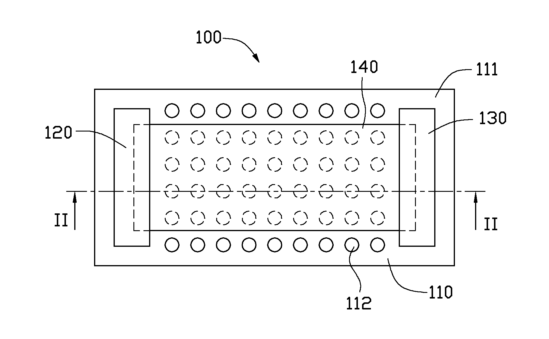
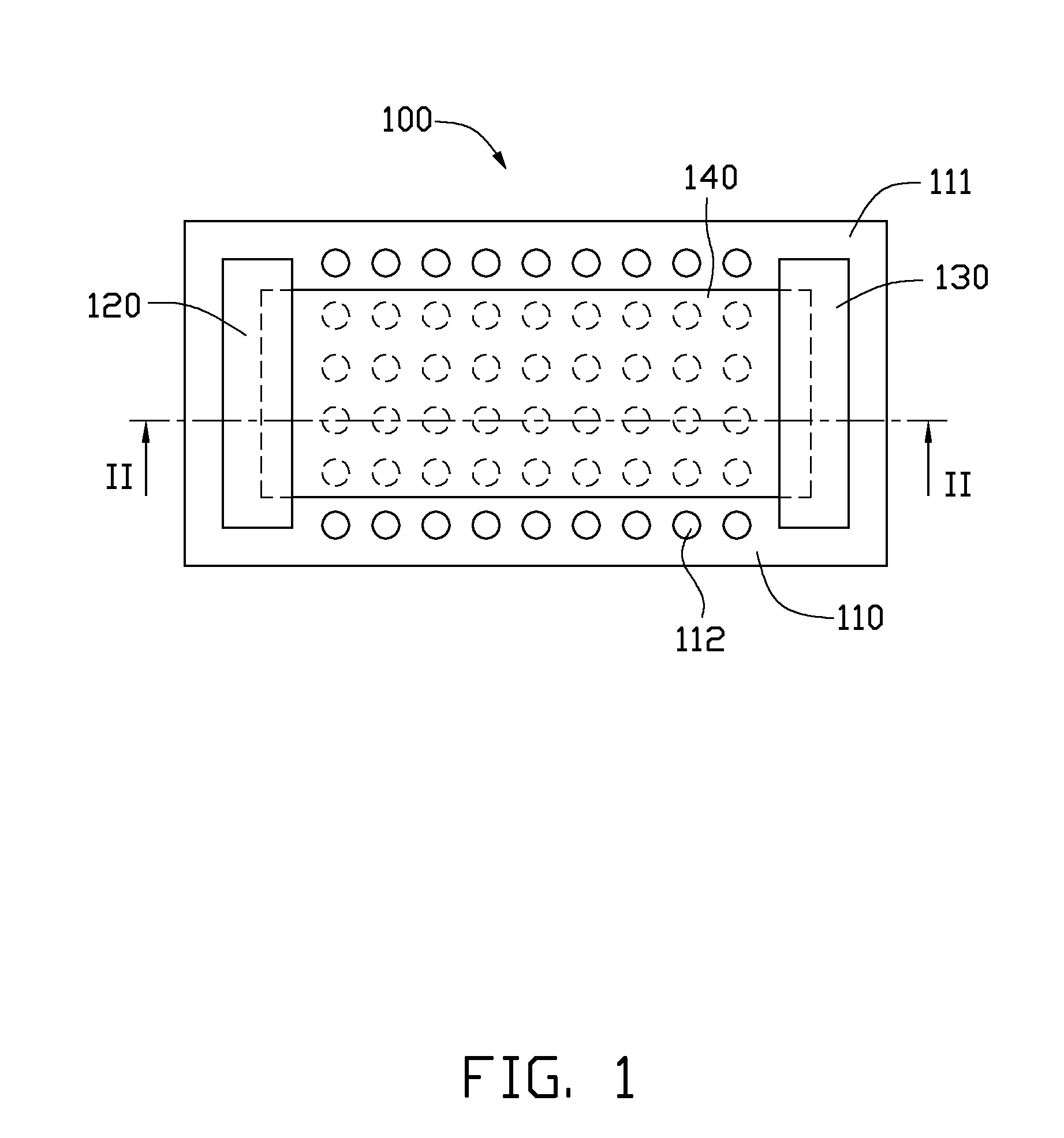
[0013]The disclosure is illustrated by way of example and not by way of limitation in the figures of the accompanying drawings in which like references indicate similar elements. It should be noted that references to “an” or “one” embodiment in this disclosure are not necessarily to the same embodiment, and such references mean at least one.

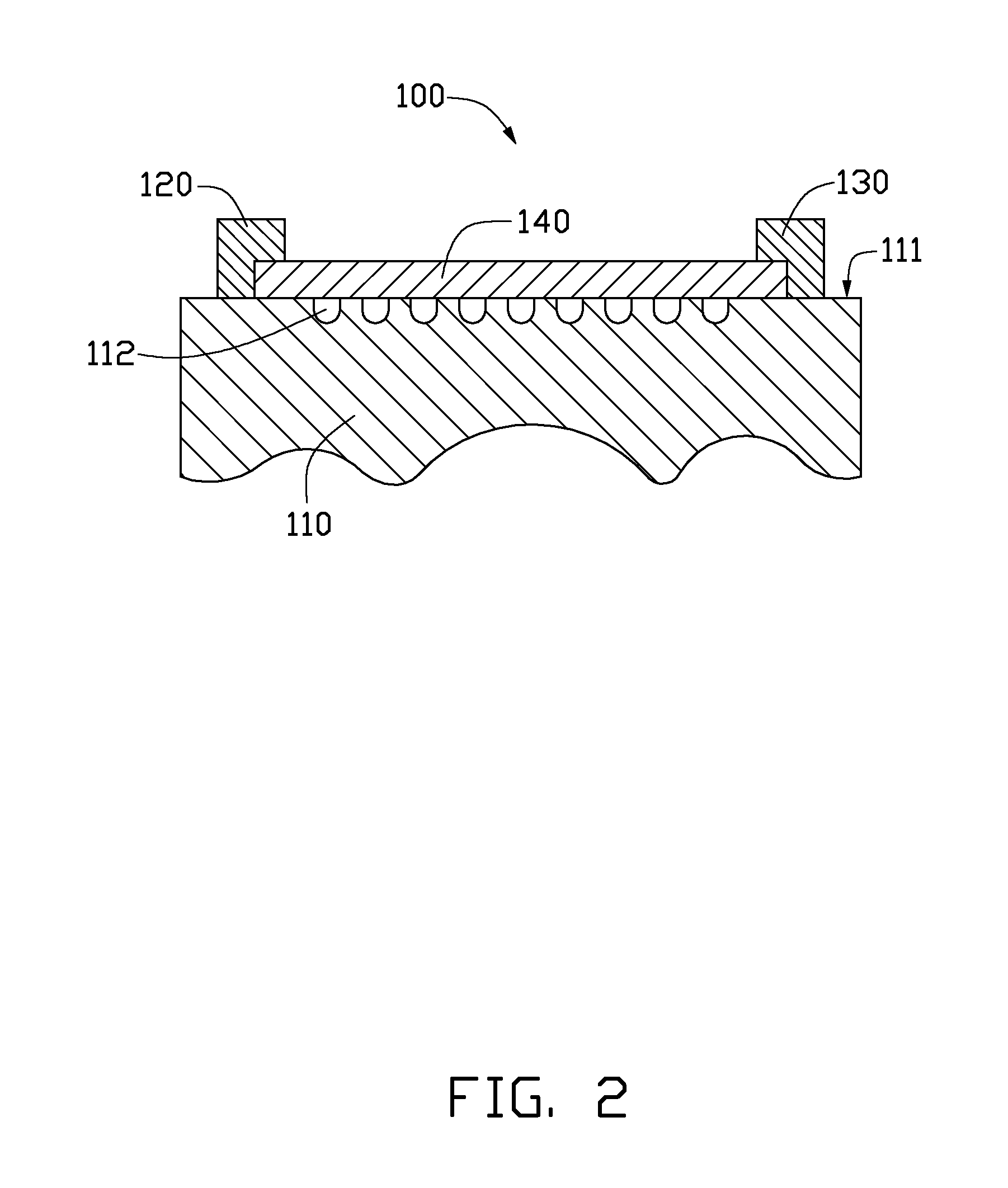
[0014]One embodiment of a room heating device 100 is illustrated in FIGS. 1-2. The room heating device 100 is installed on a supporting body 110, which can be walls, floors, ceiling, columns, or other surfaces of a room. The room heating device 100 comprises a first electrode 120, a second electrode 130, and a thermoacoustic element 140. The first electrode 120 and the second electrode 130 electrically connect to the thermoacoustic element 140. The detailed structure of the room heating device 100 will be described in the following text.

[0015]In this embodiment, the supporting body 110 has a substantially flat surface 111. The surface 111 directl...


PUM


Abstract

A room heating device includes a supporting body, a thermoacoustic element, a first electrode and a second electrode. The thermoacoustic element is disposed on the supporting body. The first electrode and the second electrode are connected to the thermoacoustic element. The first electrode is spaced apart from the second electrode.

Description

RELATED APPLICATIONS[0001]This application claims all benefits accruing under 35 U.S.C. §119 from China Patent Application No. 200910108045.X, filed on Jun. 9, 2009 in the China Intellectual Property Office, the disclosure of which is incorporated herein by reference.BACKGROUND[0002]1. Technical Field[0003]The present disclosure relates to a room heating device. Specifically, the present disclosure relates to a room heating device capable of simultaneously producing sound waves.[0004]2. Description of Related Art[0005]It is common to install electrically powered room heating devices in the walls, floor, or ceiling of a room in order to provide a controllable means of heating the room. Generally, a conventional room heating device is simply an electrical resistor, and works on the principle of Joule heating: an electric current through a resistor converts electrical energy into heat energy. However, the conventional room heating device usually only has the single function of converti...

Claims


Application Information

Patent Timeline
IPC IPC(8): F24J3/00
CPCF24H3/002H04R23/002F24H2250/10
Inventor JIANG, KAI-LILIU, LIANGFENG, CHENQIAN, LIFAN, SHOU-SHAN
Owner TSINGHUA UNIV
Why Eureka
Try Eureka