
Air outlet
a technology of air outlet and air outlet, which is applied in the field of air outlet, can solve the problems that the air outlet used in the prior art can be perceived as disadvantageous in the ventilation comfort of a small-volume rest room, and achieve the effects of high flow rate, high ventilation quality, and relatively small distance between the passenger and the air outlet according to the invention per s
- Summary
- Abstract
- Description
- Claims
- Application Information
AI Technical Summary
Benefits of technology
Problems solved by technology
Method used
Image

Examples
Embodiment Construction
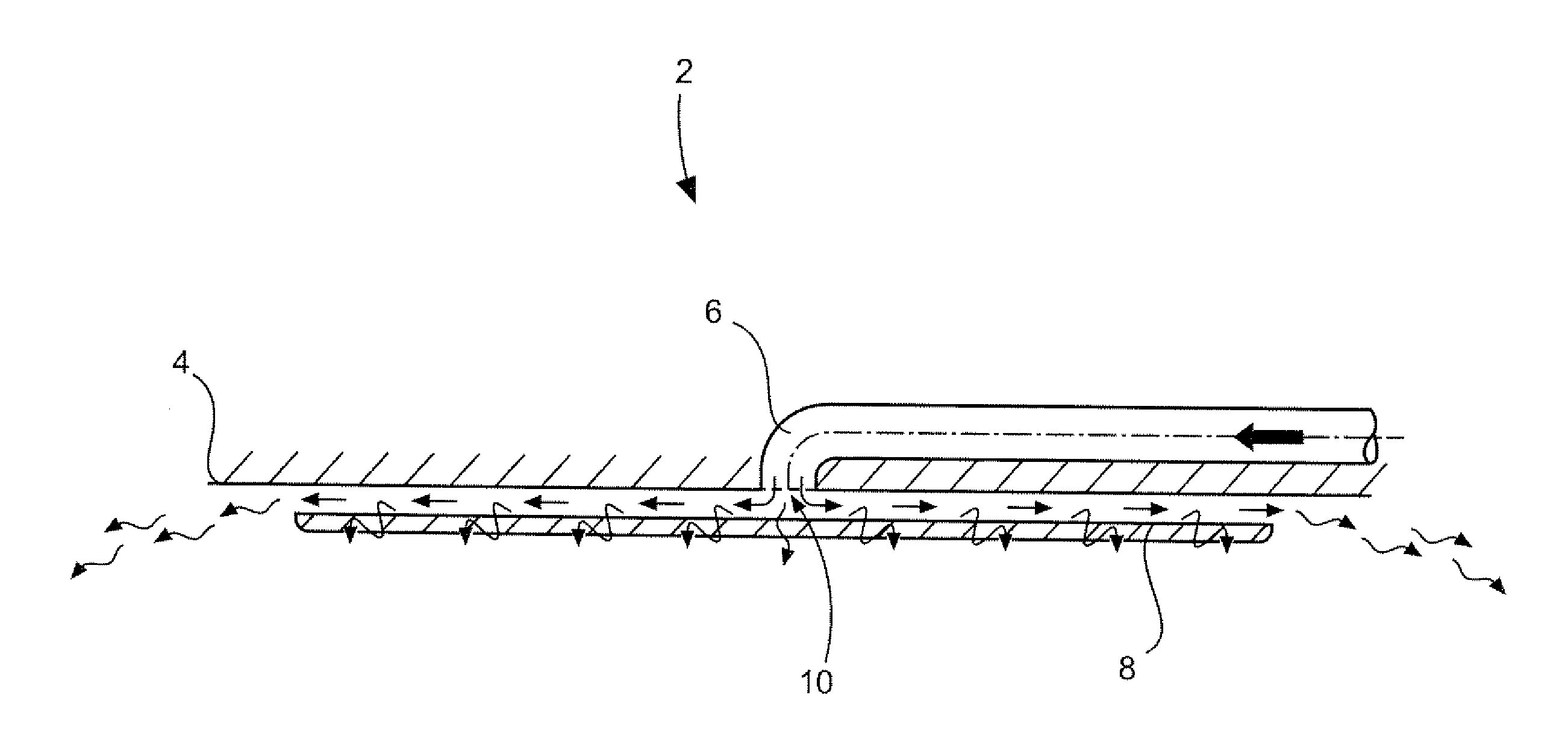
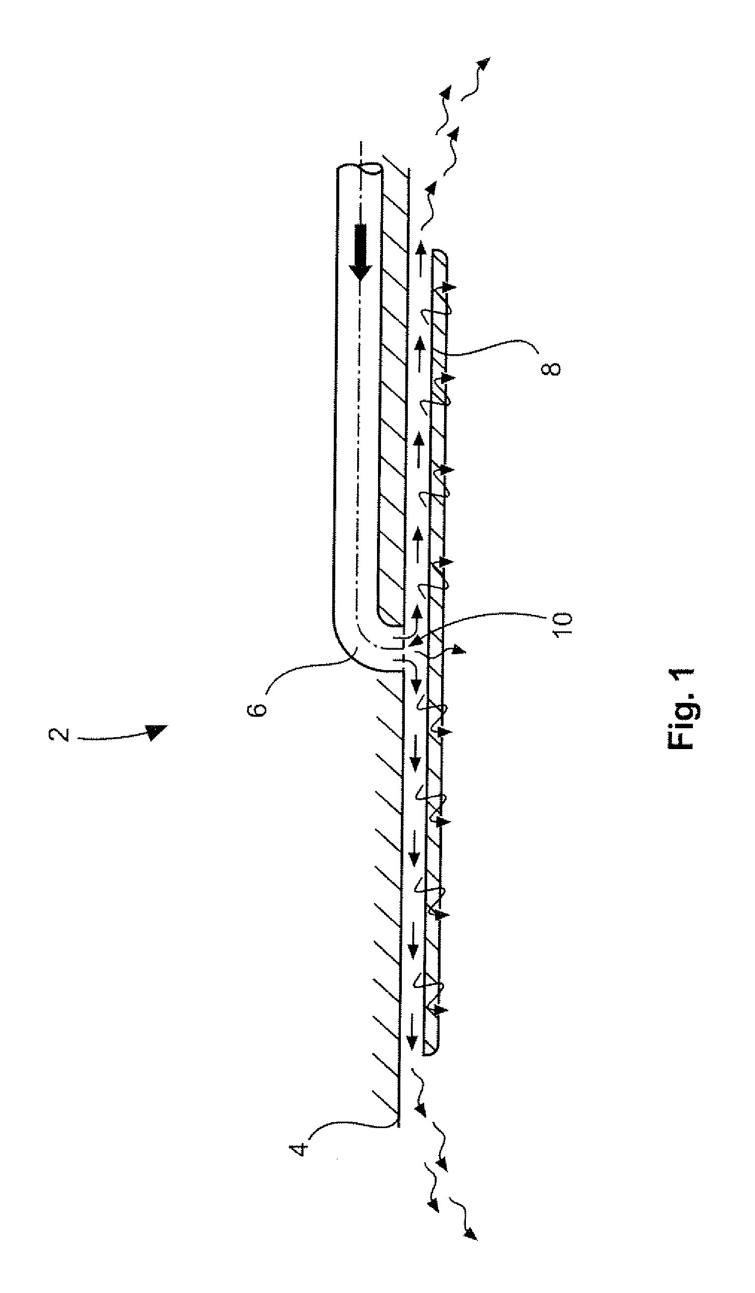
[0032]An air outlet 2 from FIG. 1 has a plane 4, for example realized as a cabin ceiling or room ceiling. An air supply line 6 that carries air empties into this plane 4. Spaced apart form the plane 4 is a baffle plate 8, which in the case shown runs parallel to the plane 4. The air supply line 6 has an opening cross section 10 directed toward the baffle plate 8. As a consequence, the air flowing out of the air supply line 6 hits the baffle plate 8, and is then radially deflected, and flows into the room to be ventilated in a planar direction from the gap between the baffle plate 8 and plane 4. Depending on how the baffle plate 8 is dimensioned, this leads to a drop in the air flow rate, and more diffuse air flows come about in the room.
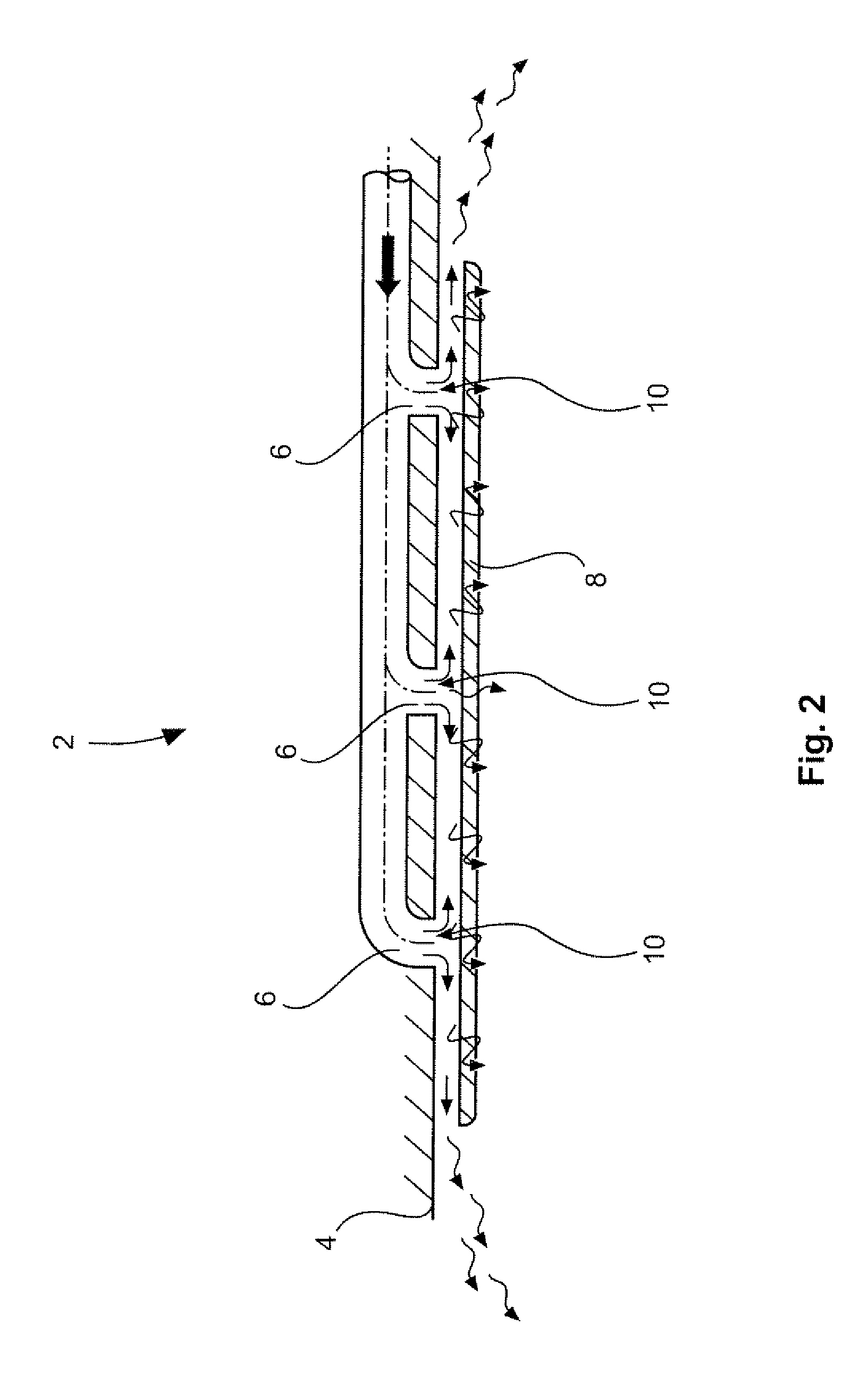
[0033]FIG. 2 shows a modification of the air outlet 2 from FIG. 1, which incorporates several air supply lines 6, which each have an opening cross section 10 directed toward the baffle plate 8. Here as well, air flows into the gap between the baffle ...
PUM
 Abstract
Description
Claims
Application Information