Changeable Connection Assembly for a Closed Suction Tube

Inactive Publication Date: 2011-01-06
CHANG TI LI
View PDF3 Cites 8 Cited by
  • Summary
  • Abstract
  • Description
  • Claims
  • Application Information

AI Technical Summary

Benefits of technology

[0008]The main objective of the invention is to provide a connection assembly for a closed suction tube and that is convenient in changing a used closed suction tube. The connection assembly has a body, a connecting end and a sealing base. The body is hollow and has a connection portion. The connection portion is hollow, is formed on the body and has a connection base. The connection base is formed on the connection portion and has a front face and two engaging channels. The front face has a top and a bottom. The engaging channels are defined respectively in the top and the bottom of the front face of the connection base and face to each other. The connecting end

Problems solved by technology

However, the conventional connection assembly for a changeable closed suction tube does not have any sealing effect to a used closed suction tube, so secretion mounted on the closed suction tube may spread out thereof.
Therefore, medial personnel easily contact with and are inflected by the secretion, and t

Method used


Image

  • Changeable Connection Assembly for a Closed Suction Tube
  • Changeable Connection Assembly for a Closed Suction Tube
  • Changeable Connection Assembly for a Closed Suction Tube

Examples


first embodiment

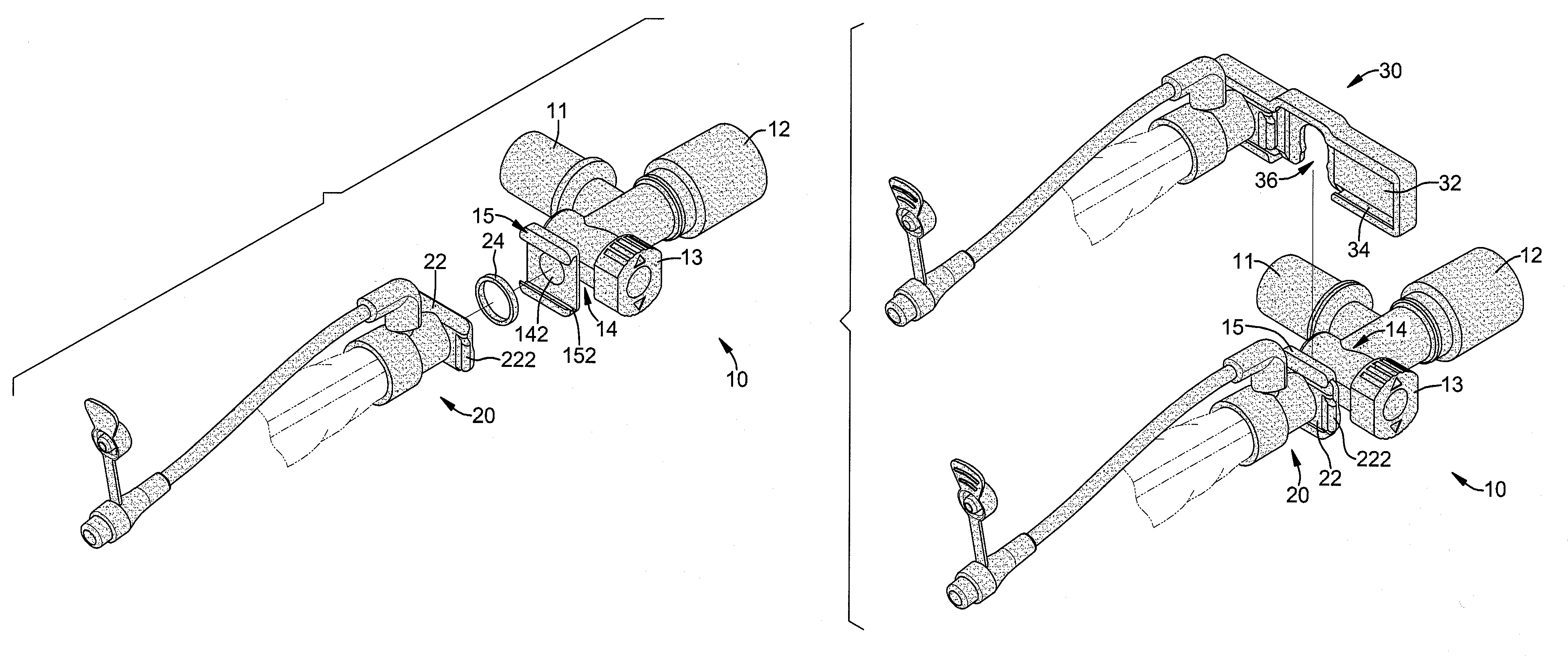
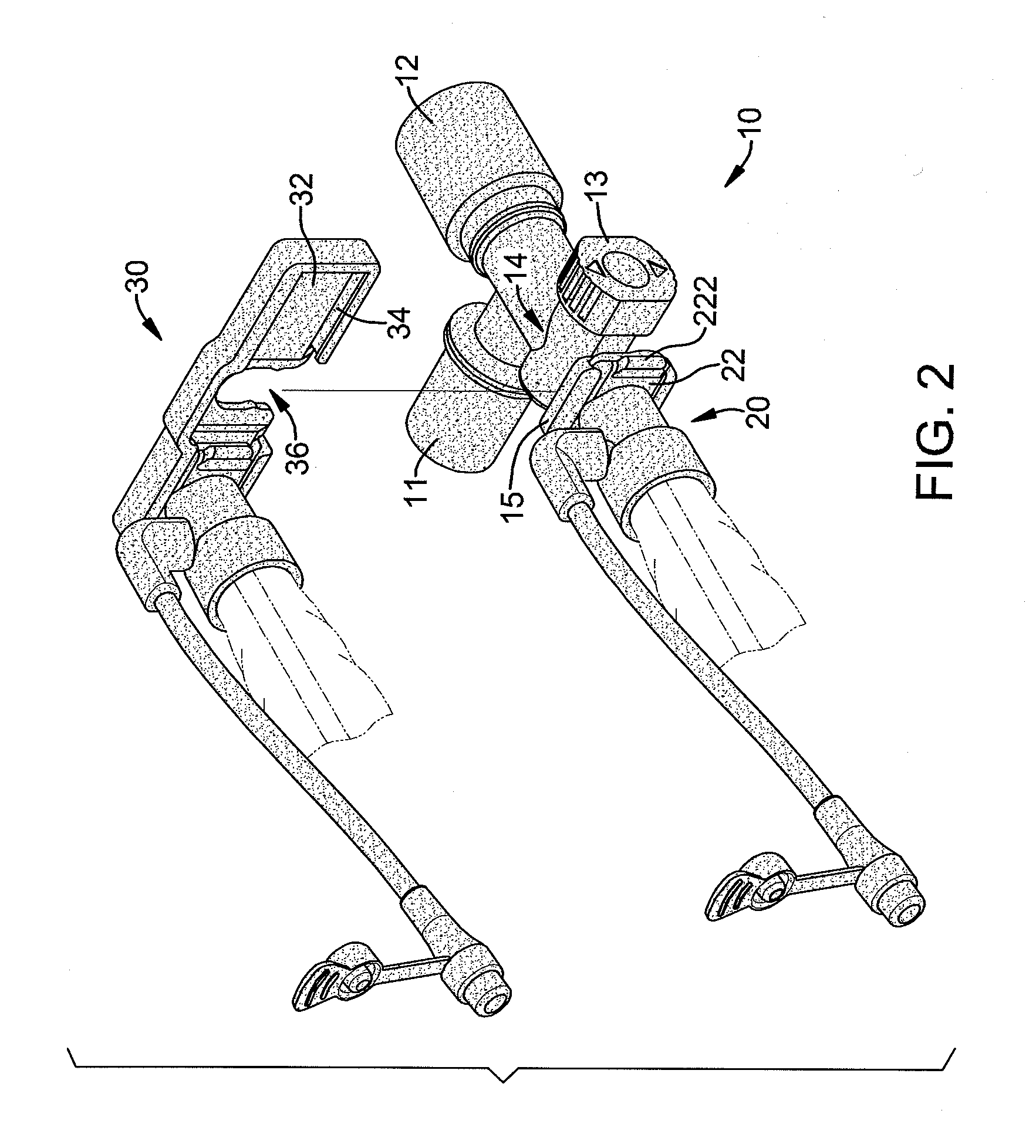
[0020]The holding assembly is formed on the connection plate (22) and engages the connection base (15) on the body (10) to securely hold the connecting end (20) on the connection base (15). In the first embodiment, the holding assembly comprises two resilient holding arms (222) formed respectively on two sides of the connection plate (22) and abutting respectively with two sides of the connection base (15). With the abutment between the resilient holding arms (222) with the sides of the connection base (15), the connection plate (22) is kept from sliding relative to the engaging channels (152) so that the connecting end (20) will not be detached from the connection base (15) unintentionally.

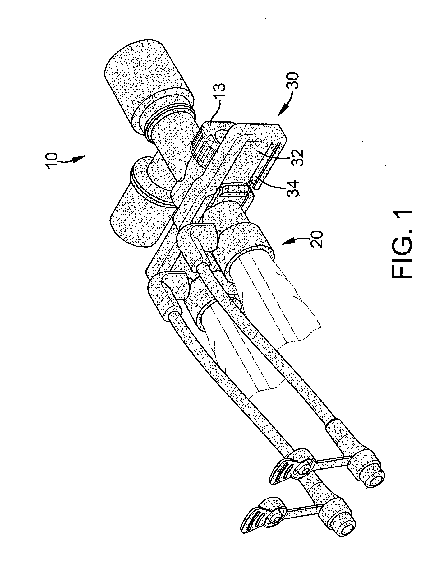
[0021]The sealing base (30) is mounted detachably on the connection portion (14) and comprises a sealing face (32), a guiding channel (34) and a holding notch (36). The sealing face (32) is flush with the front face of the connection base (15) when the sealing base (30) is mounted on the connecti...

second embodiment

[0025]With reference to FIGS. 6 to 8, in a connection assembly in accordance with the present invention, the holding assembly on the connection plate (22A) comprises a resilient holding arm (222A) formed on one of the edges of the connection plate (22A) that engages one of the engaging channels (152A) in the connection base (15A). The resilient holding arm (222A) has an engaging block (224) formed on the resilient holding arm (222A). The connection base (15A) further has an engaging hole (154) defined in the connection base (15A) and engaging the engaging block (224) on the resilient holding arm (222A). With the engagement between the engaging block (224) on the resilient holding arm (222A) and the engaging hole (154), the connecting end (20A) will not be disconnected from the connection base (15A) unintentionally. Furthermore, the sealing base (30A) further has a pushing block (38) formed in the guiding channel (34A). When the sealing base (30A) is attached to the body (10A), the p...


PUM


Abstract

A connection assembly has a body, a connecting tube and a sealing base. The body is hollow and has a connection portion. The connection portion has a connection base having a front face and two engaging channels. The engaging channels are defined in the front face and face to each other. The connecting end with a suction tube is detachably attached to the front face of the connection base, communicates with the connection portion and has a connection plate. The connection plate held slidably in the engaging channels in the connection base. The sealing base is mounted detachably on the connection portion and has a sealing face and a guiding channel. The sealing face is flush with the front face of the connection base. The guiding channel is defined around the sealing face and communicates with the engaging channels in the connection base.

Description

BACKGROUND OF THE INVENTION[0001]1. Field of the Invention[0002]The present invention relates to a connection assembly, and more particularly to a changeable connection assembly for a closed suction tube.[0003]2. Description of Related Art[0004]A closed suction tube is used to draw secretion from a patient with a drawing force provided by a hospital vacuum source. Furthermore, the closed suction tube is used to perform the secretion suction on patient while providing ventilation simultaneously. Consequently, this can reduce bad influences to the vital sign of the patient.[0005]However, the conventional connection assembly for a changeable closed suction tube does not have any sealing effect to a used closed suction tube, so secretion mounted on the closed suction tube may spread out thereof. Therefore, medial personnel easily contact with and are inflected by the secretion, and this easily causes cross inflection between patients and medial personnel in a hospital.[0006]In addition,...

Claims


Application Information

Patent Timeline
IPC IPC(8): F16L37/05
CPCA61M1/008A61M1/0086F16L39/00F16L37/26A61M1/84A61M1/86
Inventor CHANG, TI-LI
Owner CHANG TI LI
Why Eureka
Try Eureka