Pressure Bandage

a technology of pressure bandage and bandage, which is applied in the field of pressure bandage, can solve the problems of inconvenient use, treatment parts of users cannot be maintained, and users cannot move freely, and achieve the effect of free movement of users

Inactive Publication Date: 2011-01-13
NAT PINGTUNG UNIV OF SCI & TECH
View PDF8 Cites 1 Cited by
  • Summary
  • Abstract
  • Description
  • Claims
  • Application Information

AI Technical Summary

Benefits of technology

[0008]An objective of the present invention is to provide a pressure bandage allowing free movement of the user using the pressure bandage.

Problems solved by technology

In the conventional pressurized treatment, the user can not move freely due to limitation of the position of the pump for delivering the fluid to the treatment part via the conduit for maintaining the pressure at the treatment part.
Thus, the banding portion must be removed when the user is intended to move beyond the range of the conduit due to limitation of the length of the conduit and / or the position of the pump.
As a result, the treatment part of the user can not be maintained in the pressurized status, which is inconvenient to use.

Method used


Image

  • Pressure Bandage
  • Pressure Bandage
  • Pressure Bandage

Examples


Embodiment Construction

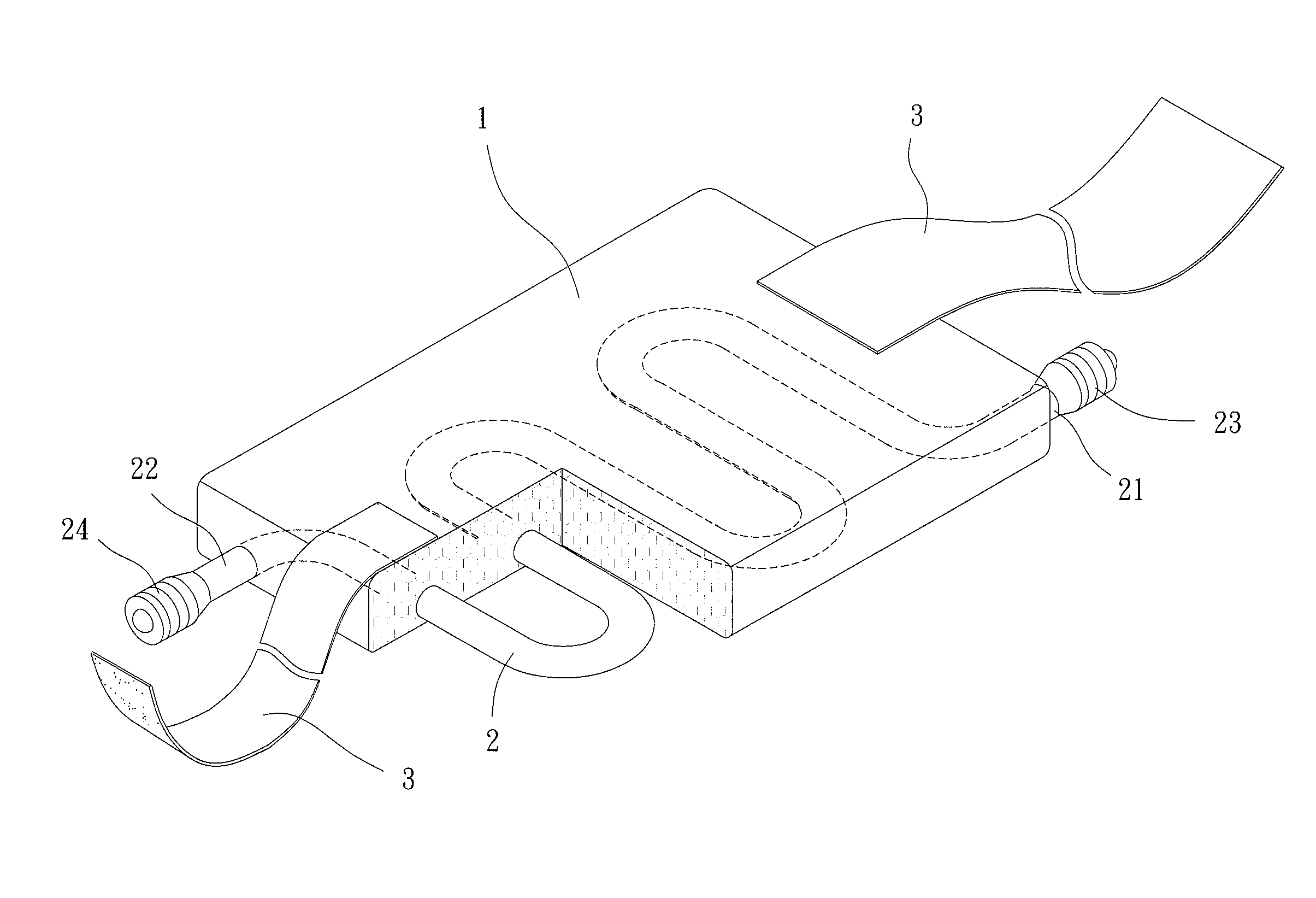
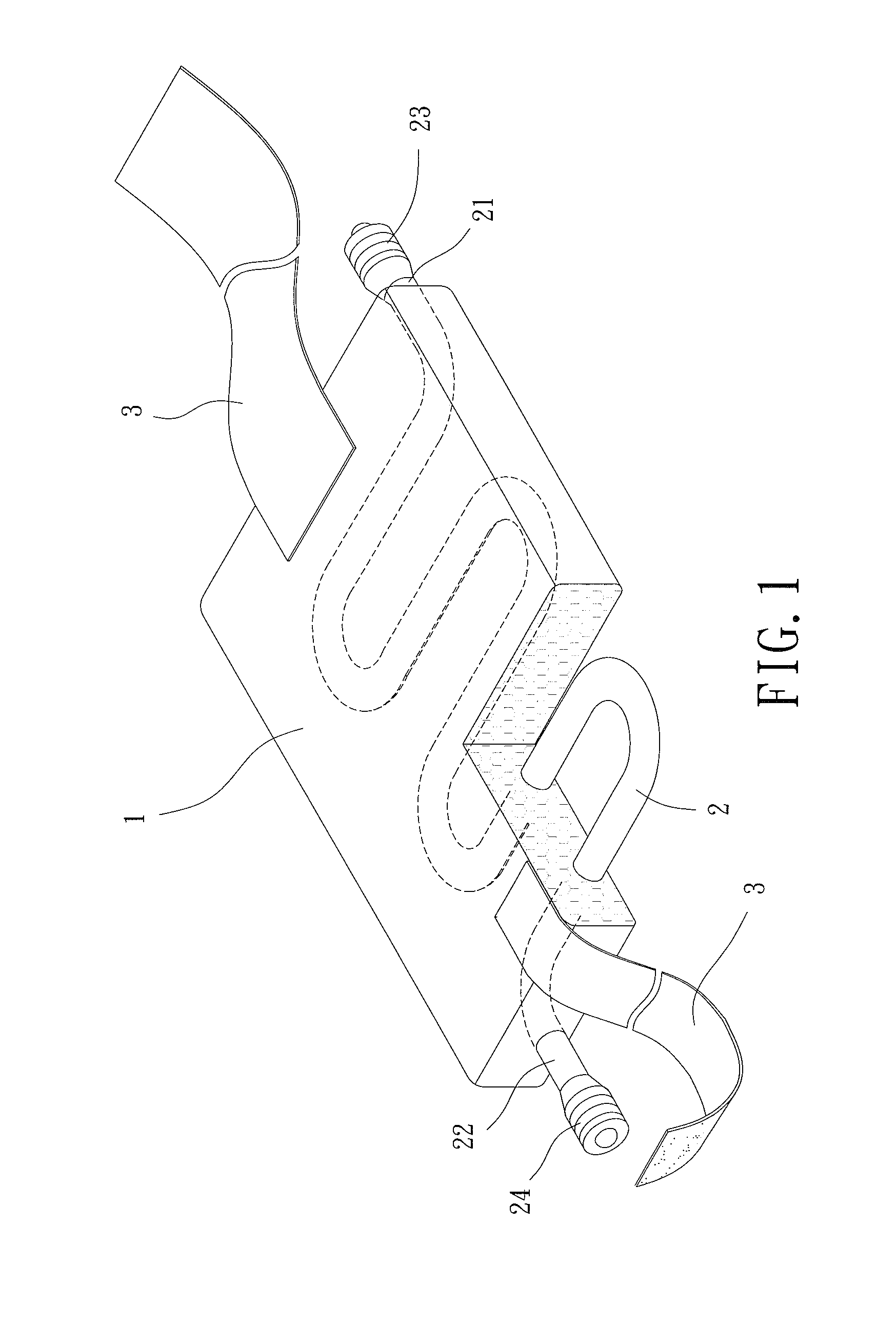
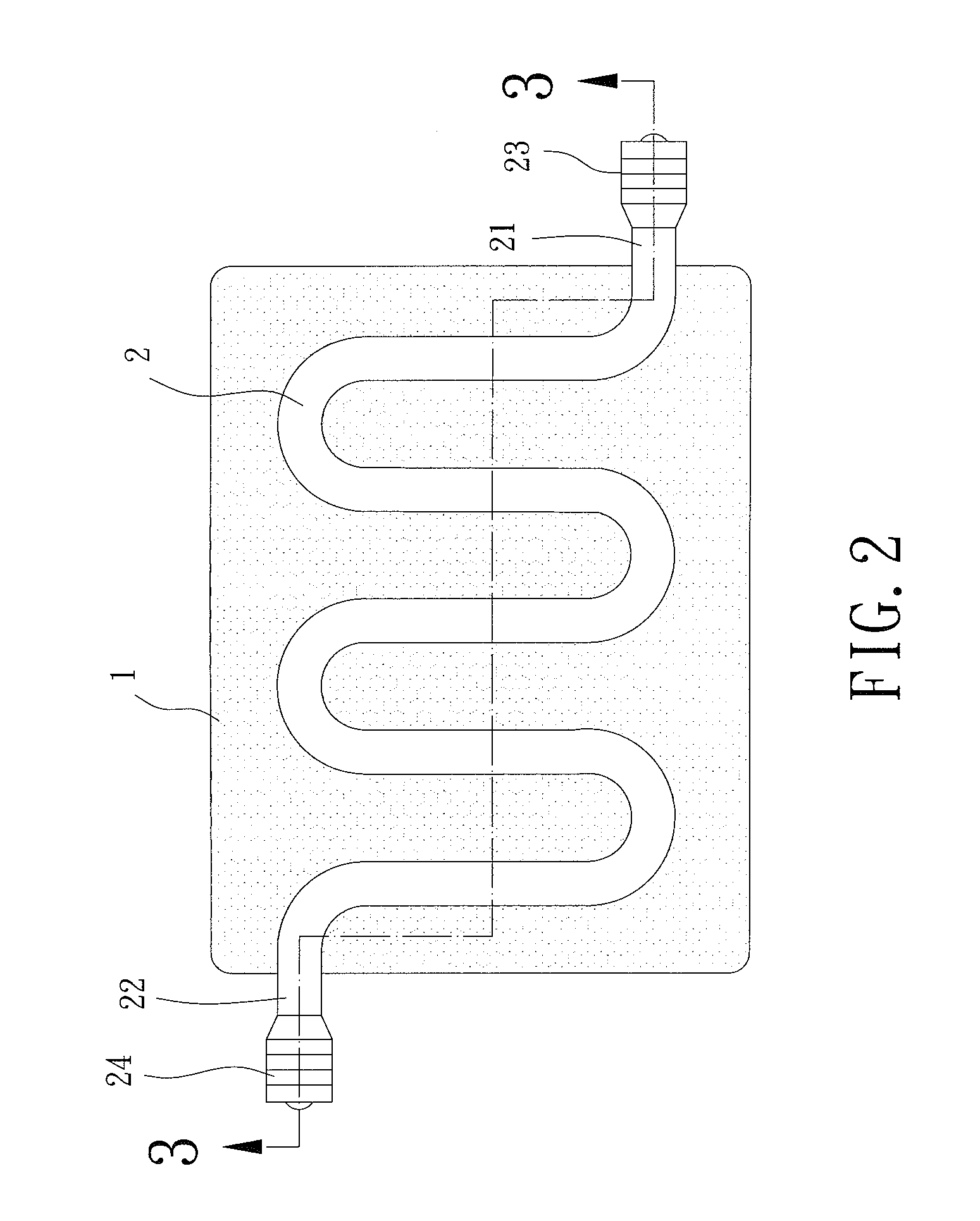
[0021]Referring to FIGS. 1, 2 and 5, a pressure bandage is disclosed according to a first embodiment of the invention. The pressure bandage comprises a banding portion 1, a container 2 received in the banding portion 1, and a fixing member 3 adapted to fix the banding portion 1 and the container 2 on a treatment part 92 of a body portion 94 of a user requiring pressurized treatment.

[0022]In the preferred form shown, the banding portion 1 is made of shapeable sponge, elastic bandage, or the like. The banding portion 1 can be of any desired shape and size.

[0023]The container 2 can be a conduit or a bladder for receiving a fluid. In the first embodiment shown, the container 2 is in the form of a conduit made of polypropylene, polyethylene or rubber, etc. The container 2 is fixed in the banding portion 1 and adjacent to a contact surface of the banding portion 1. In the preferred form shown, the contact surface is the bottom surface of the banding portion 1. The container 2 includes a f...


PUM


Abstract

A pressure bandage comprises a banding portion, a container received a fluid and a fixing member. The container has a first and a second connecting portions, and the first and second connecting portions are respectively protruded from the opposite sides of the banding portion. At least one check valve is mounted in at least one of the first and second connecting portions for delivering the fluid into the container. The fixing member is adapted to fix the banding portion to a treatment part.

Description

BACKGROUND OF THE INVENTION[0001]1. Field of the Invention[0002]The present invention generally relates to a pressure bandage and, more particularly, to a pressure bandage that allows free movement of the user using the pressure bandage.[0003]2. Description of the Related Art[0004]Conventional pressurized treatment includes a negative pressure therapy for healing the open wound of the hypodermis tissue, and a positive pressure therapy for healing the wound of the epithelium tissue.[0005]Specifically, the negative pressure therapy is to reduce the pressure of a treatment part of a user by a pump for facilitating the open wound healing.[0006]On the other hand, the positive pressure therapy includes use of a banding portion fixed to the treatment part of the user requiring pressurized treatment. A pump delivers a fluid in a conduit such that the pressure at the banding portion is greater than the atmospheric pressure, maintaining the treatment part in a pressurized status to inhibit gr...

Claims


Application Information

Patent Timeline
Patent Type & Authority Applications(United States)
IPC IPC(8): A61B17/00
CPCA61B17/1325
Inventor LU, WEI-HUACHEN, YUNG-CHUANCHEN, LI-WEN
Owner NAT PINGTUNG UNIV OF SCI & TECH
Why Eureka
Try Eureka