Pressure Bandage

a bandage and pressure technology, applied in the field of pressure bandage, can solve the problems of inconvenient use, treatment part of the user cannot be maintained, user cannot move freely,

Active Publication Date: 2011-02-17
NAT PINGTUNG UNIV OF SCI & TECH
View PDF8 Cites 8 Cited by
  • Summary
  • Abstract
  • Description
  • Claims
  • Application Information

AI Technical Summary

Benefits of technology

[0007]An objective of the present invention is to provide a pressure bandage allowing a user to adjust the pressure when the difference between the positive pressure in the pressure bandage and the atmospheric pressure becomes small, maintaining the pressure bandage in a positive pressure status.

Problems solved by technology

In the conventional pressurized treatment, the user can not move freely due to limitation of the position of the pump for delivering the fluid to the treatment part via the conduit for maintaining the pressure at the treatment part.
Thus, the banding portion must be removed when the user is intended to move beyond the range of the conduit due to limitation of the length of the conduit and / or the position of the pump.
As a result, the treatment part of the user can not be maintained in the pressurized status, which is inconvenient to use.
However, the treatment effect is limited if the treatment involves an inflammatory, swollen wound or an epithelial tissue requiring ease of pain.

Method used


Image

  • Pressure Bandage
  • Pressure Bandage
  • Pressure Bandage

Examples


Embodiment Construction

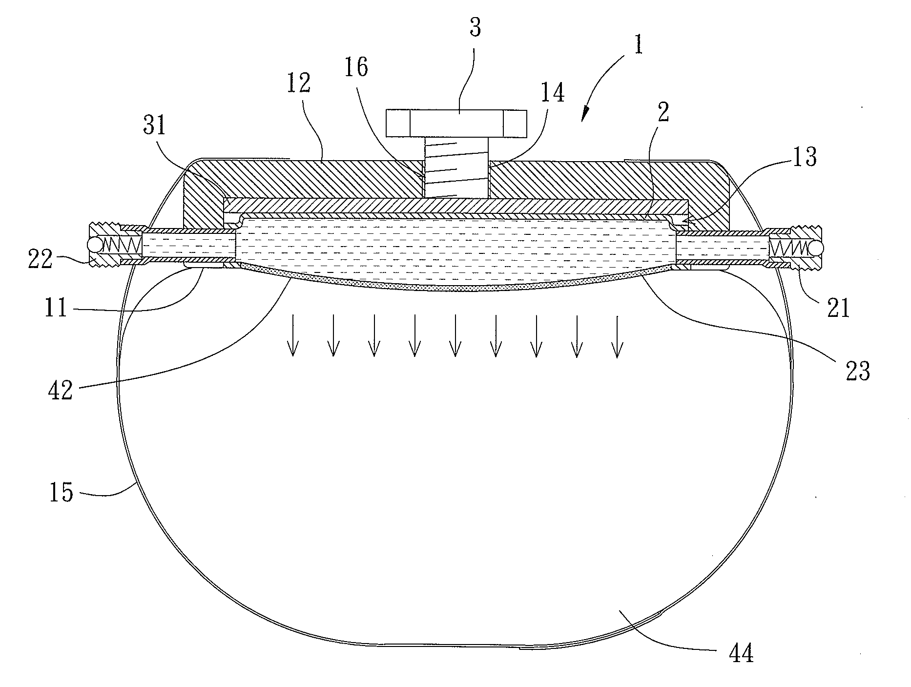
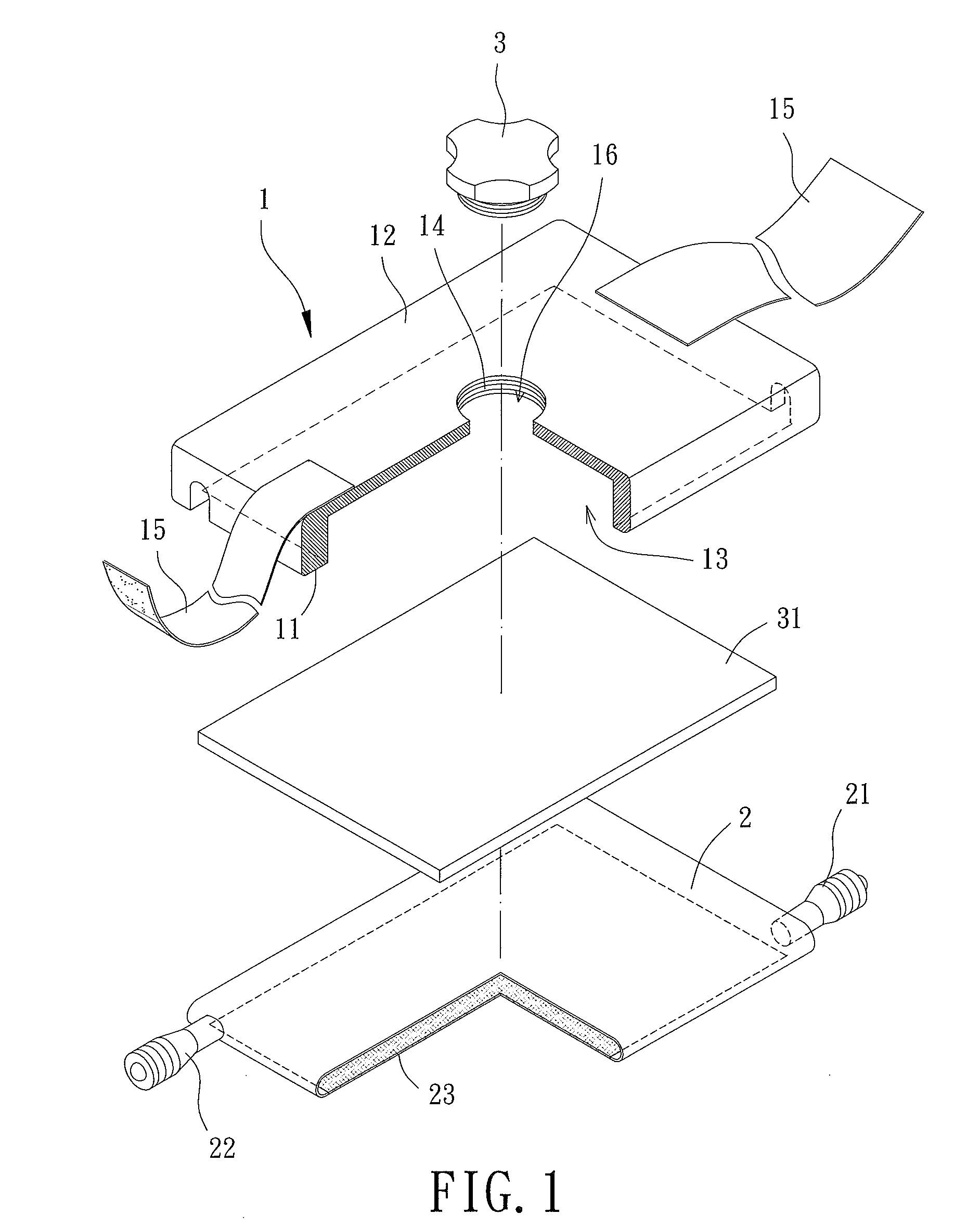
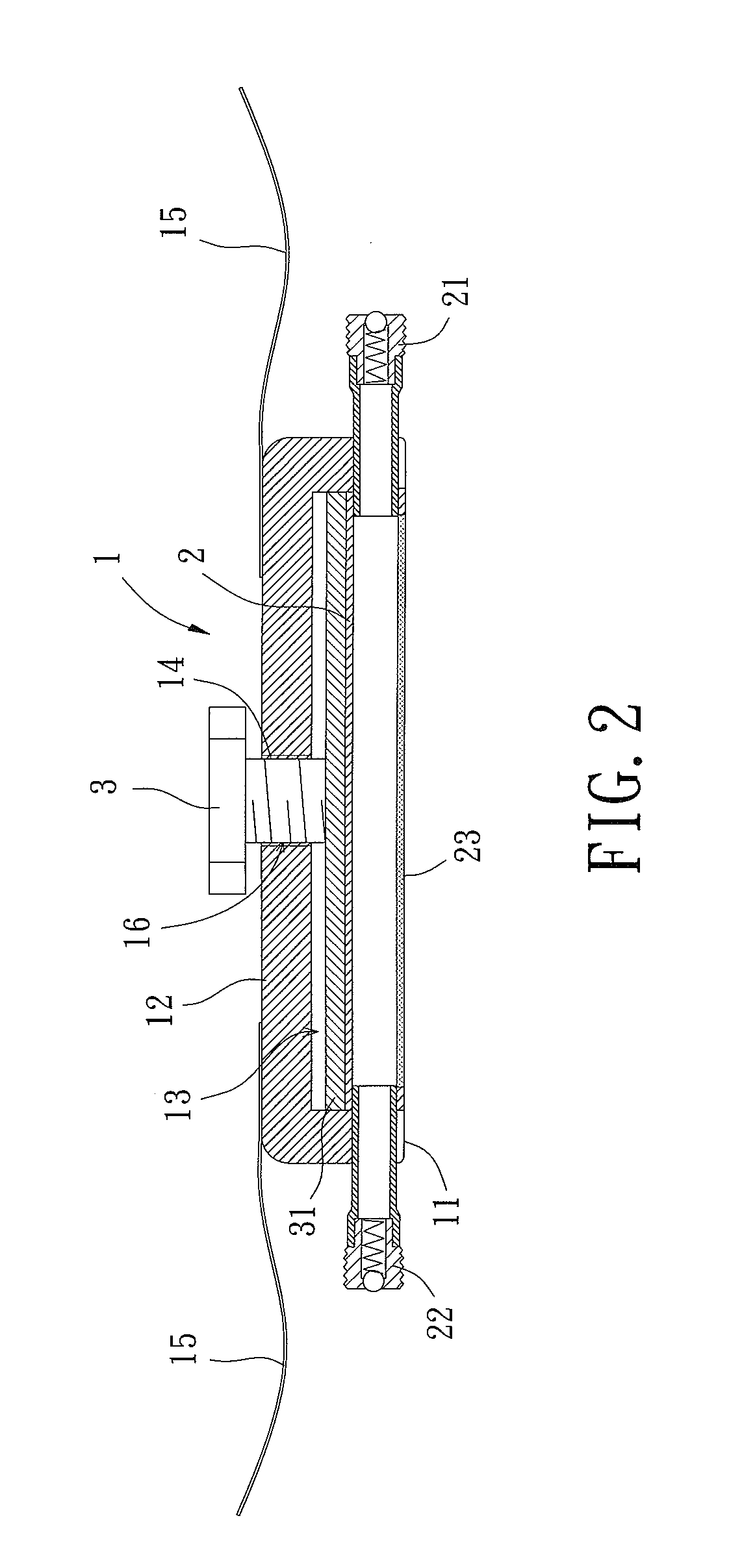
[0021]A pressure bandage according to the preferred teachings of the present invention is shown in the drawings and generally includes a banding portion 1, a bladder 2 received in the banding portion 1, and a control member 3 for imparting a pressure to the bladder 2.

[0022]The banding portion 1 is made of shapeable sponge, elastic bandage, or the like. The banding portion 1 can be of any desired shape and size. In the preferred form shown, the banding portion 1 includes opposite first and second sides 11 and 12. A chamber 13 is formed in the first side 11 of the banding portion 1. The second side 12 of the banding portion 1 includes an engaging section 14 having an engaging hole 16 in communication with the chamber 13. In order to easily fix the banding portion 1 to a treatment part 42 of a body portion 44 of a user, the banding portion 1 further includes a fixing member 15. In the most preferred form shown, the fixing member 15 includes two straps respectively having a hook fastene...


PUM


Abstract

A pressure bandage includes a banding portion having opposite first and second sides. A chamber is formed in the first side of the banding portion. The second side of the banding portion includes a hole in communication with the chamber. A bladder is received in the chamber and receives a fluid. The bladder includes an infiltratable surface permeable to the fluid. The infiltratable surface of the bladder and the first side of the banding portion face the same direction. The fluid received in the bladder is permeable out of the bladder via the infiltratable surface. A control member is engaged with the hole of the banding portion and imparts a pressure to the bladder. The hole can be a screw hole, and the control member includes a knob threadedly engaged with the screw hole such that the knob is rotatable to adjust the pressure imparted to the bladder.

Description

BACKGROUND OF THE INVENTION[0001]1. Field of the Invention[0002]The present invention relates to a pressure bandage and, more particularly, to a pressure bandage allowing a user to adjust a pressure imparted to a treatment part of the user requiring pressurized treatment.[0003]2. Description of the Related Art[0004]Conventional pressurized treatment includes use of a banding portion fixed to a treatment part of a user requiring pressurized treatment. A pump delivers a fluid in a conduit such that the pressure at the banding portion is greater than the atmospheric pressure, maintaining the treatment part in a pressurized status to inhibit growth of the tissue at the treatment part.[0005]In the conventional pressurized treatment, the user can not move freely due to limitation of the position of the pump for delivering the fluid to the treatment part via the conduit for maintaining the pressure at the treatment part. Thus, the banding portion must be removed when the user is intended t...

Claims


Application Information

Patent Timeline
Patent Type & Authority Applications(United States)
IPC IPC(8): A61F13/00A61M35/00
CPCA61M35/00A61F13/08
Inventor LU, WEI-HUACHEN, YUNG-CHUANCHIANG, TING-LUNG
Owner NAT PINGTUNG UNIV OF SCI & TECH
Why Eureka
Try Eureka