Fixing unit having a plurality of heaters, image forming apparatus and method of determining temperature detecting position of temperature sensor
a technology of fixing unit and heater, which is applied in the direction of electrographic process apparatus, instruments, optics, etc., can solve the problems of temperature of the fixing member exceeding the set temperature, the fixing unit cannot be used for a waiting time until, etc., and achieves satisfactory image, and safe heating of the fixing member
- Summary
- Abstract
- Description
- Claims
- Application Information
AI Technical Summary
Benefits of technology
Problems solved by technology
Method used
Image
Examples
first embodiment
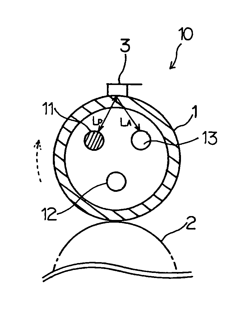
[0064]FIG. 5 is a cross sectional view showing a part of the fixing unit according to the present invention. In FIG. 5 and FIGS. 6 through 15 which will be described later, those parts which are essentially the same as those corresponding parts in FIG. 3 are designated by the same reference numerals, and a description thereof will be omitted.
[0065]A fixing unit 10 shown in FIG. 5 includes a fixing roller 1, a pressure roller 2 and a temperature sensor 3. The fixing roller 1 includes three heaters 11, 12 and 13 which heat the fixing roller 1 from the inside. The pressure roller 2 presses against the fixing roller 1 at a predetermined nip pressure. The temperature sensor 3 contacts an outer peripheral surface of the fixing roller 1 and outputs a temperature detection signal indicative of a surface temperature of the fixing roller 1 that is detected thereby.
[0066]In this embodiment, the fixing roller 1 has a hollow cylindrical shape. However, a fixing member is not limited to the fixin...
second embodiment
[0092]FIG. 9 is a cross sectional view showing a part of the first modification of the fixing unit.
[0093]In a fixing unit 50 shown in FIG. 9, rod-shaped heaters 51, 52, 53 and 54 are disposed symmetrically about the center shaft of the fixing roller 1 at circumferential positions separated by a predetermined distance from the inner peripheral surface of the fixing roller 1. The heaters 51 and 53 receive power from a battery, such as a capacitor, and heat the fixing roller 1 by radiating heat towards the inner peripheral surface of the fixing roller 1. The power from the battery, which is supplied to the heaters 51 and 53, is controlled. In other words, the power from the battery, to be supplied to the heaters 51 and 53, may be turned ON and OFF. On the other hand, the heaters 52 and 54 receive power from an external power supply such as a commercial A.C. power supply, and heat the fixing roller 1 by radiating heat towards the inner peripheral surface of the fixing roller 1. The powe...
third embodiment
[0117]FIG. 16 is a perspective view showing a part of the fixing unit. FIG. 17 is a side view showing a fixing roller shown in FIG. 16. FIG. 18 is a cross sectional view of the fixing unit cut along a line A—A in FIG. 16, and FIG. 19 is a cross sectional view of the fixing unit cut along a line B—B in FIG. 16. Further, FIG. 20 is a diagram showing amounts of heat generated by heater parts of the heaters. In FIGS. 16 through 19, those parts which are essentially the same as those corresponding parts shown in FIGS. 5 through 14 are designated by the same reference numerals, and a description thereof will be omitted.
[0118]In this embodiment, the heater 11 of a fixing unit 400 is made up of a single heater part 111, the heater 12 is made up of a center heater part 112, and the heater 13 is made up of a pair of end heater parts 113-1 and 113-2, as shown in FIG. 17. A temperature sensor 3-1 provided at a position corresponding to the center heater part 112, so as to detect the surface tem...
PUM
 Abstract
Description
Claims
Application Information
 - R&D
- Intellectual Property
- Life Sciences
- Materials
- Tech Scout
- Unparalleled Data Quality
- Higher Quality Content
- 60% Fewer Hallucinations
Browse by: Latest US Patents, China's latest patents, Technical Efficacy Thesaurus, Application Domain, Technology Topic, Popular Technical Reports.
© 2025 PatSnap. All rights reserved.Legal|Privacy policy|Modern Slavery Act Transparency Statement|Sitemap|About US| Contact US: help@patsnap.com


