Brake control apparatus and control lever therefor

a technology of brake control apparatus and control lever, which is applied in the direction of mechanical control devices, instruments, cycle equipment, etc., can solve problems such as unsatisfactory mounting configuration

Active Publication Date: 2011-02-10
SHIMANO INC
View PDF23 Cites 43 Cited by
  • Summary
  • Abstract
  • Description
  • Claims
  • Application Information

AI Technical Summary

Benefits of technology

[0006]An embodiment of the present invention advantageously provides a control lever comprising a body portion, a mounting portion, at least one mounting screw, and a lever portion. The body portion has a first section configured to fit within an interior of a bar opening, where the first section is configured to house at least a portion of a control mechanism, and where the first section has an inclined surface on an outer surface thereof. The mounting portion is configured to slide on the inclined surface. The at least one mounting screw is configured to connect the mounting portion to the body portion. The lever portion is connected to the body portion and is configured to actuate the control mechanism. The at least one mounting screw is configured to slide the mounting portion along the inclined surface so as to push the mounting portion and a side of the first section against an inner surface of the bar opening in order to mount the body portion to the bar opening.
[0007]A further embodiment of the present invention advantageously provides a hydraulic brake control apparatus comprising a hydraulic brake control mechanism including a hydraulic brake pressure cylinder, and a control lever. The control lever includes: a body portion having a first section configured to fit within an interior of a bar opening, where the first section houses the hydraulic brake pressure cylinder, and where the first section has an inclined surface on an outer surface thereof; a mounting portion configured to slide on the inclined surface; at least one mounting screw configured to connect the mounting portion to the body portion; and a lever portion connected to the body portion and configured to actuate the control mechanism. The at least one mounting screw is configured to slide the mounting portion along the inclined surface so as to push the mounting portion and a side of the first section against an inner surface of the bar opening in order to mount the body portion to the bar opening.
[0008]A still further embodiment of the present invention advantageously provides a control lever comprising a body portion, means for mounting the body portion to a bar opening, and a lever portion. The body portion has a first section configured to fit within an interior of the bar opening, where the first section is configured to house at least a portion of a control mechanism, and where the first section has an inclined surface on an outer surface thereof. The means for mounting includes a mounting portion for sliding along the inclined surface so as to push the mounting portion and a side of the first section against an inner surface of the bar opening. The lever portion is connected to the body portion and configured to actuate the control mechanism.

Problems solved by technology

However, such a mounting configuration may not be ideal, since many of the components of the hydraulic brake lever may be exposed and therefore susceptible to damage or environmental factors.

Method used


Image

  • Brake control apparatus and control lever therefor
  • Brake control apparatus and control lever therefor
  • Brake control apparatus and control lever therefor

Examples


Embodiment Construction

[0018]Embodiments of the present invention will be described hereinafter with reference to the accompanying drawings. In the following description, the constituent elements having substantially the same function and arrangement are denoted by the same reference numerals, and repetitive descriptions will be made only when necessary.

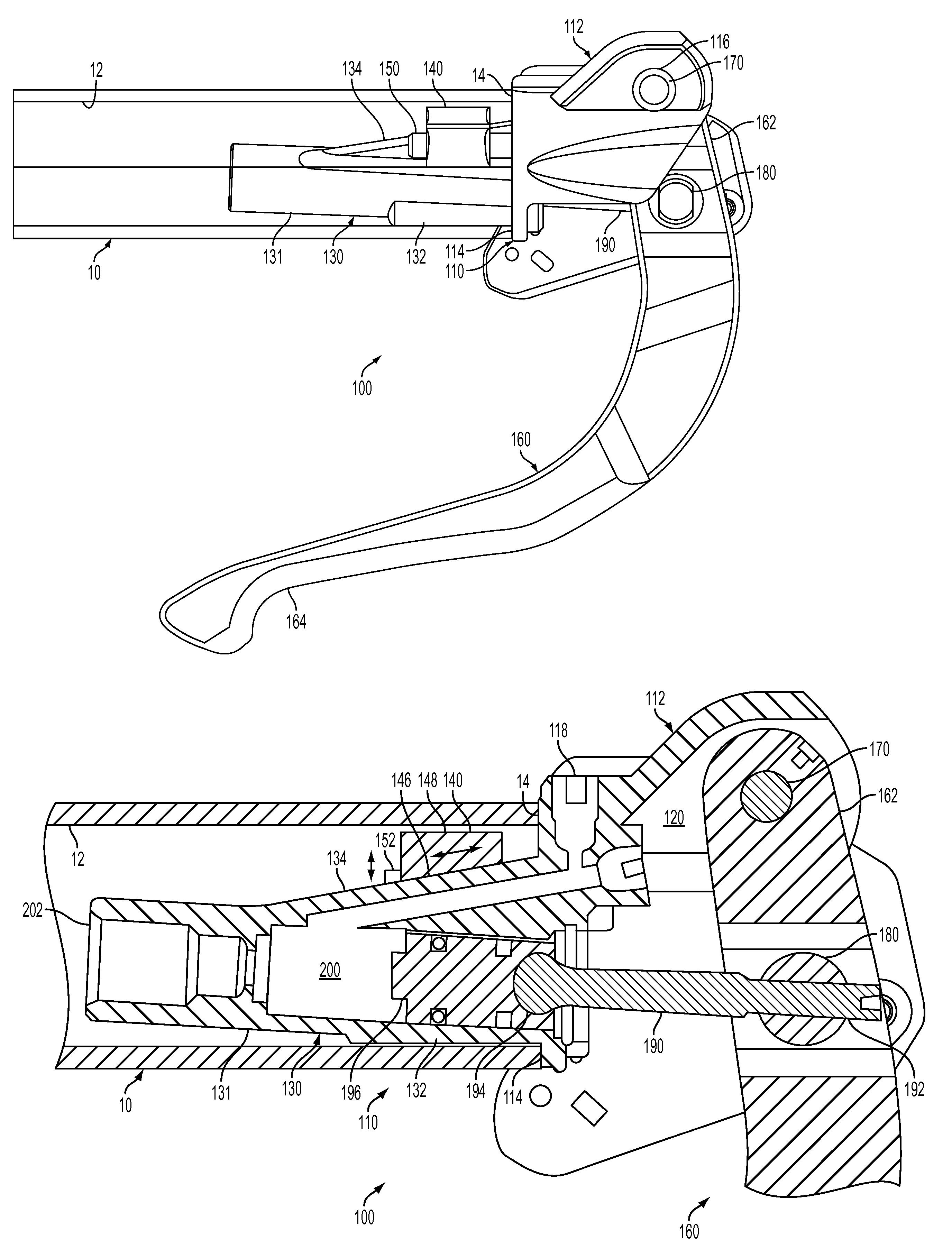
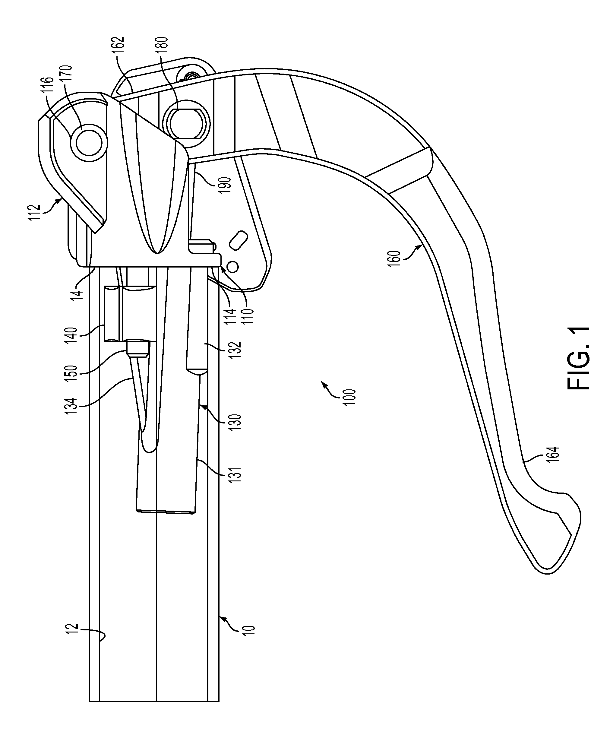
[0019]FIG. 1 is a front, elevational view of a hydraulic brake control apparatus including a control lever 100, which is mounted to a handlebar 10, according to an embodiment of the present invention. In FIG. 1, for the sake of simplicity and ease of depiction, the handlebar 10 is shown as being transparent so that components of the hydraulic brake control apparatus that are received within the handlebar 10 can be seen therethrough.

[0020]FIG. 1 depicts a handlebar 10 that is a tubular member having a hollow interior with an inner surface 12 and an open terminal end 14. The handlebar 10 can be, for example, for a bicycle or other vehicle that utilizes such ...


PUM


Abstract

A control lever including a body portion, a mounting portion, at least one mounting screw, and a lever portion. The body portion has a first section configured to fit within an interior of a bar opening, where the first section is configured to house at least a portion of a control mechanism and has an inclined surface on an outer surface thereof. The mounting portion is configured to slide on the inclined surface, and the mounting screw connects the mounting portion to the body portion. The lever portion is connected to the body portion and is configured to actuate the control mechanism. The mounting screw is configured to slide the mounting portion along the inclined surface so as to push the mounting portion and a side of the first section against an inner surface of the bar opening in order to mount the body portion to the bar opening.

Description

BACKGROUND OF THE INVENTION[0001]1. Field of the Invention[0002]The present invention relates to a control lever, and more particularly to a control lever with a portion embedded in a bar opening of a bicycle handlebar.[0003]2. Discussion of the Background[0004]Hydraulic brake systems have been utilized on bicycles to provide powerful, safe, and stable braking effects. Such hydraulic brake systems can include a brake lever mounted on a handlebar of a bicycle, a disc brake mounted beside a wheel of the bicycle, and a hydraulic tube interconnecting the brake lever and the disc brake. Due to the size and shape of the components of conventional hydraulic brake levers, such brake levers are typically mounted on the handlebar using a bracket affixed to an outer circumference of the handlebar. However, such a mounting configuration may not be ideal, since many of the components of the hydraulic brake lever may be exposed and therefore susceptible to damage or environmental factors.[0005]Ac...

Claims


Application Information

Patent Timeline
Patent Type & Authority Applications(United States)
IPC IPC(8): B60T11/00G05G11/00
CPCB60T7/102B60T11/165Y10T74/2028B62K23/06B60T11/18
Inventor MATSUSHITA, TATSUYA
Owner SHIMANO INC
Why Eureka
Try Eureka