Multifunctional switch and detector assembly for a medical imaging system including the same

a multi-functional switch and detector technology, applied in the field of imaging detectors, can solve the problems of limited battery life, limited amount of time that the detector can be operated on a single battery charge, and continuous reduction of the battery life in both modes of operation, so as to reduce the power consumption of a portable x-ray detector

Active Publication Date: 2011-03-03
GENERAL ELECTRIC CO
View PDF31 Cites 40 Cited by
  • Summary
  • Abstract
  • Description
  • Claims
  • Application Information

AI Technical Summary

Benefits of technology

[0005]In one embodiment, a portable detector control circuit for reducing power consumption of a portable x-ray detector is provided. The detector control circuit includes a multi-function switch coupled to the portable detector, and a detector control mo

Problems solved by technology

To make the portable detector lightweight, the capacity of the battery is limited.
Thus, the amount of time that the detector can be operated on a single battery charge is also limited.
However, when the portable detector is not being used in to perform the imaging operation, the portable detector remains fully energized to enable the imaging syst

Method used


Image

  • Multifunctional switch and detector assembly for a medical imaging system including the same
  • Multifunctional switch and detector assembly for a medical imaging system including the same
  • Multifunctional switch and detector assembly for a medical imaging system including the same

Examples


Embodiment Construction

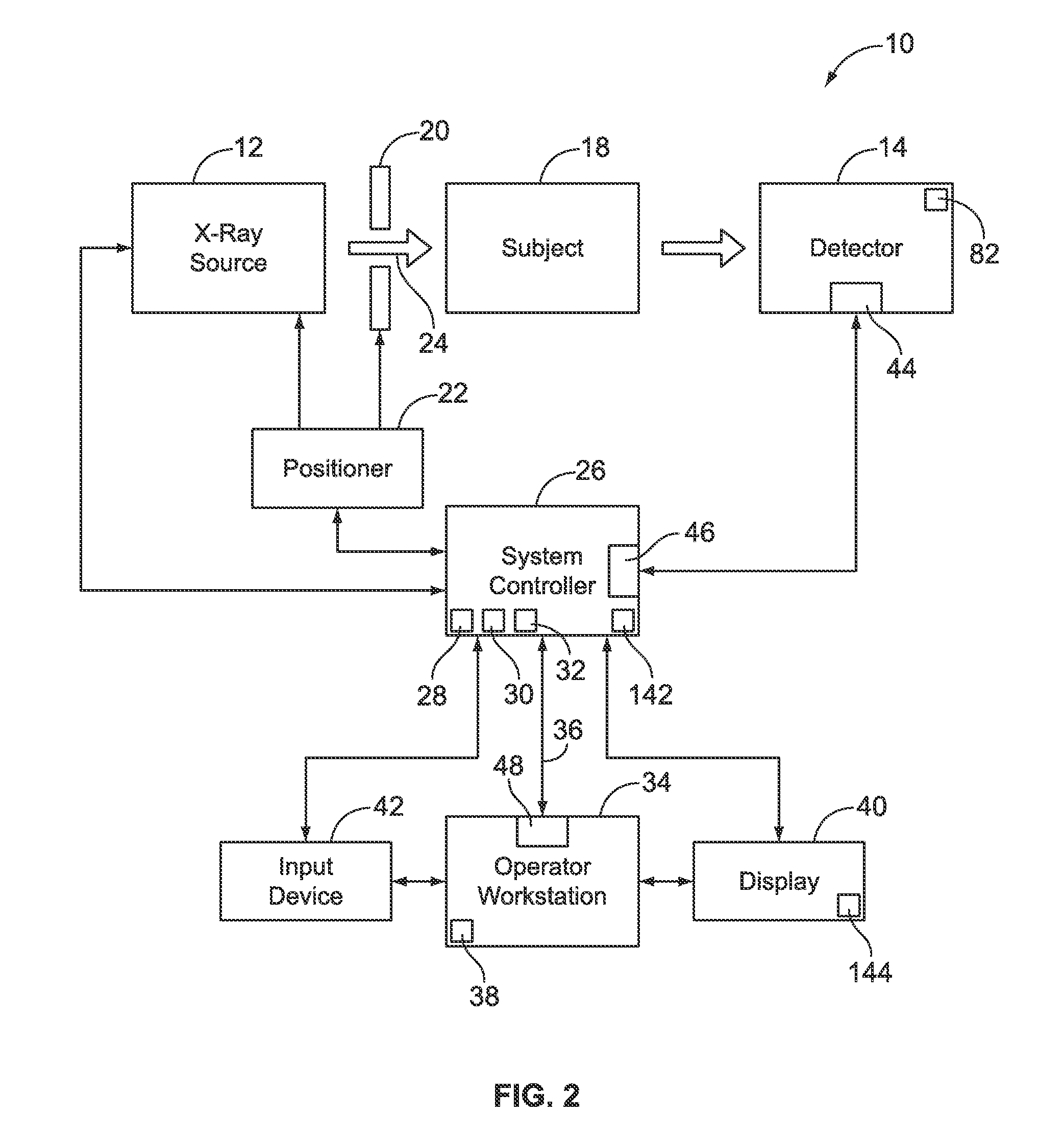
[0016]The foregoing summary, as well as the following detailed description of certain embodiments of the present invention, will be better understood when read in conjunction with the appended drawings. To the extent that the figures illustrate diagrams of the functional blocks of various embodiments, the functional blocks are not necessarily indicative of the division between hardware circuitry. Thus, for example, one or more of the functional blocks (e.g., processors or memories) may be implemented in a single piece of hardware (e.g., a general purpose signal processor or a block of random access memory, hard disk, or the like). Similarly, the programs may be stand alone programs, may be incorporated as subroutines in an operating system, may be functions in an installed software package, and the like. It should be understood that the various embodiments are not limited to the arrangements and instrumentality shown in the drawings.

[0017]As used herein, an element or step recited i...


PUM


Abstract

A control circuit for a portable x-ray medical imaging system detector. The control circuit operates to reduce power consumption of the portable x-ray detector. The detector control circuit includes a multi-function switch coupled to the portable detector, and a detector control module installed in the portable detector, the detector control module receiving an input from the multi-function switch and based on the received input reconfiguring the portable detector from a first operational mode to a different second operational mode. A portable detector including the detector control circuit and a method of operating the portable detector are also provided.

Description

BACKGROUND OF THE INVENTION[0001]The subject matter disclosed herein relates generally to imaging detectors, and more particularly to a circuit for performing multiple functions on a portable imaging detector.[0002]In various medical imaging applications, a portable imaging detector may be utilized to perform medical imaging. At least one conventional portable x-ray detector includes an external casing that is typically formed of metal. The external casing includes a front cover, a back cover, and a plurality of sides that together form the external casing. The portable x-ray detector also includes a plurality of detector elements that are disposed proximate to the portable x-ray device front cover. During operation, x-rays pass through the front cover and impinge on the plurality of detector elements. The detector elements produce an electrical signal that represents the intensity of the impinging X-ray beam and hence allows estimation of the attenuation of the beam as the beam pas...

Claims


Application Information

Patent Timeline
IPC IPC(8): G08B3/00H05G1/56
CPCA61B5/055A61B6/4405A61B6/467A61B6/56A61B8/00A61B8/4405Y02B60/1282A61B6/4233G06F1/3206G06F1/3287A61B6/548A61B6/4494A61B6/508A61B2560/0209Y02D10/00
Inventor LIU, JAMES ZHENGSHEPETRICK, SCOTT WILLIAMLANGLER, DONALD FAYETTEMCBROOM, GARY VERNONSCHLEY, ROY ALLAN
Owner GENERAL ELECTRIC CO
Why Eureka
Try Eureka