Kitchen appliance

Inactive Publication Date: 2011-03-24
KONINKLIJKE PHILIPS ELECTRONICS NV
View PDF8 Cites 1 Cited by
  • Summary
  • Abstract
  • Description
  • Claims
  • Application Information

AI Technical Summary

Benefits of technology

[0011]More in particular it is an object of the present invention to provide an improved kitchen appliance which comprises a bowl that is easily and securely attachable to a base station, and provides improved cleanability and usability of the different parts comprised in the kitchen appliance.
[0025]Coupling of the tool by the coupling member of the bowl by means of the cam portions results in a very close fit between the head and socket. Furthermore, no need for further manual operations exists to place the tool in the bowl. In fact, due to the cam portions the connection between the head and socket (and consequently the bowl and the tool) is self-finding. This reduces the number of manual operations to be done by a person using the kitchen appliance according to the invention, increasing the ease of use. Furthermore, because the tool is pulled onto the coupling member a very secure coupling is achieved.

Problems solved by technology

A drawback of the kitchen appliance of U.S. Pat. No. 5,908,242 A is that the bowl must be carefully placed onto the support, so that the pin is allowed to engage the angled slot or engagement surface of the member.
Yet another drawback of the kitchen appliance know from U.S. Pat. No. 5,908,242 A is the fact that coupling between the bowl and the support is effected by means of a pin that engages the slot provided in the wall of the member.
Furthermore, the number of parts that make up the locking connection of the known kitchen appliance is relatively large and the connection is complex.
A drawback of the known kitchen appliance is related to the design of the bowl and in particular to the tubular element that forms a through opening through which the drive shaft extends.
Furthermore, as the tubular element extends only along a part of the height of the bowl, the bowl cannot be completely filled with foodstuffs.
Also, the tubular element is difficult to clean as it is designed as a relatively narrow tube so as to closely enclose the drive shaft protruding through it.

Method used


Image

  • Kitchen appliance
  • Kitchen appliance
  • Kitchen appliance

Examples


Embodiment Construction

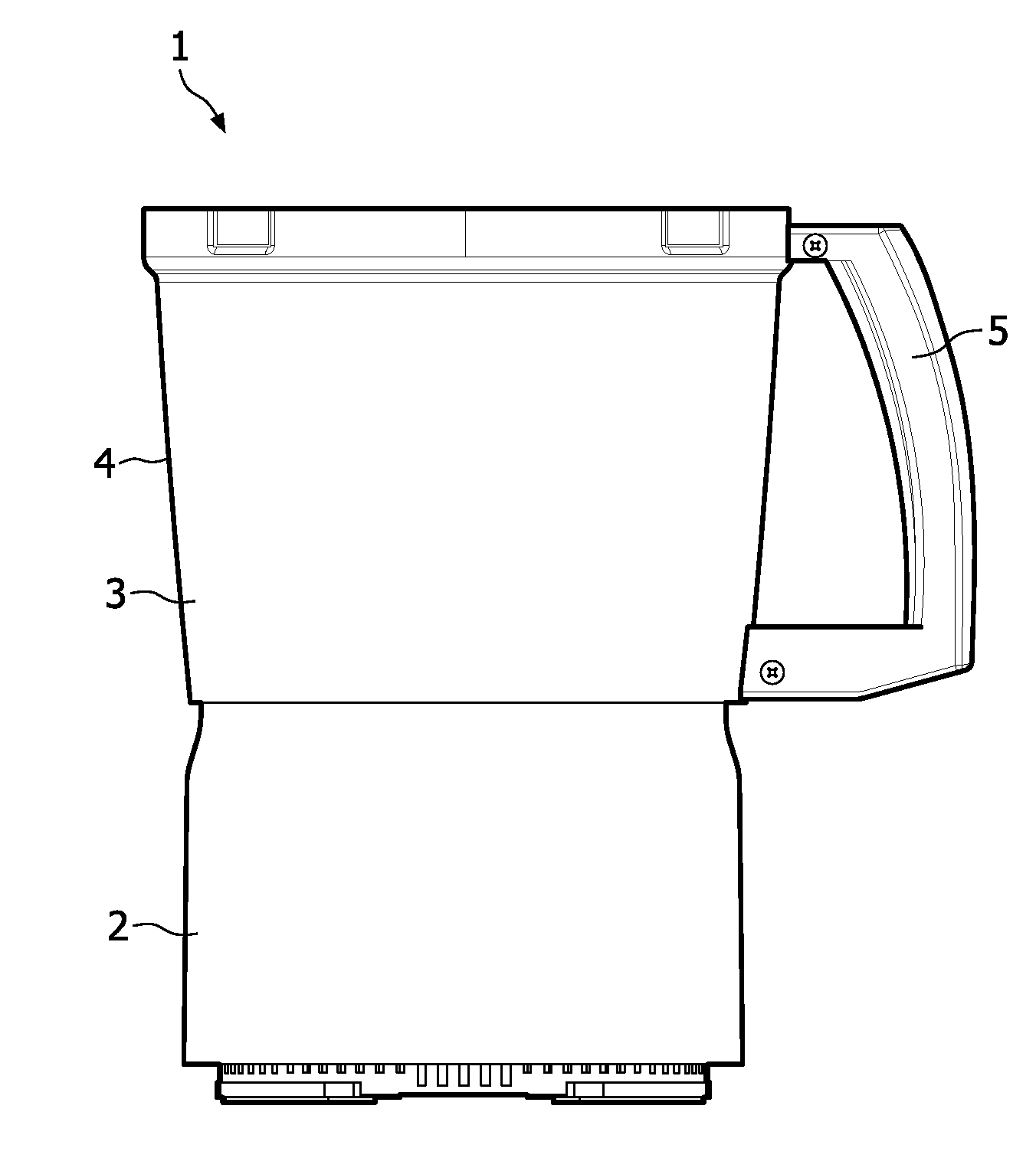
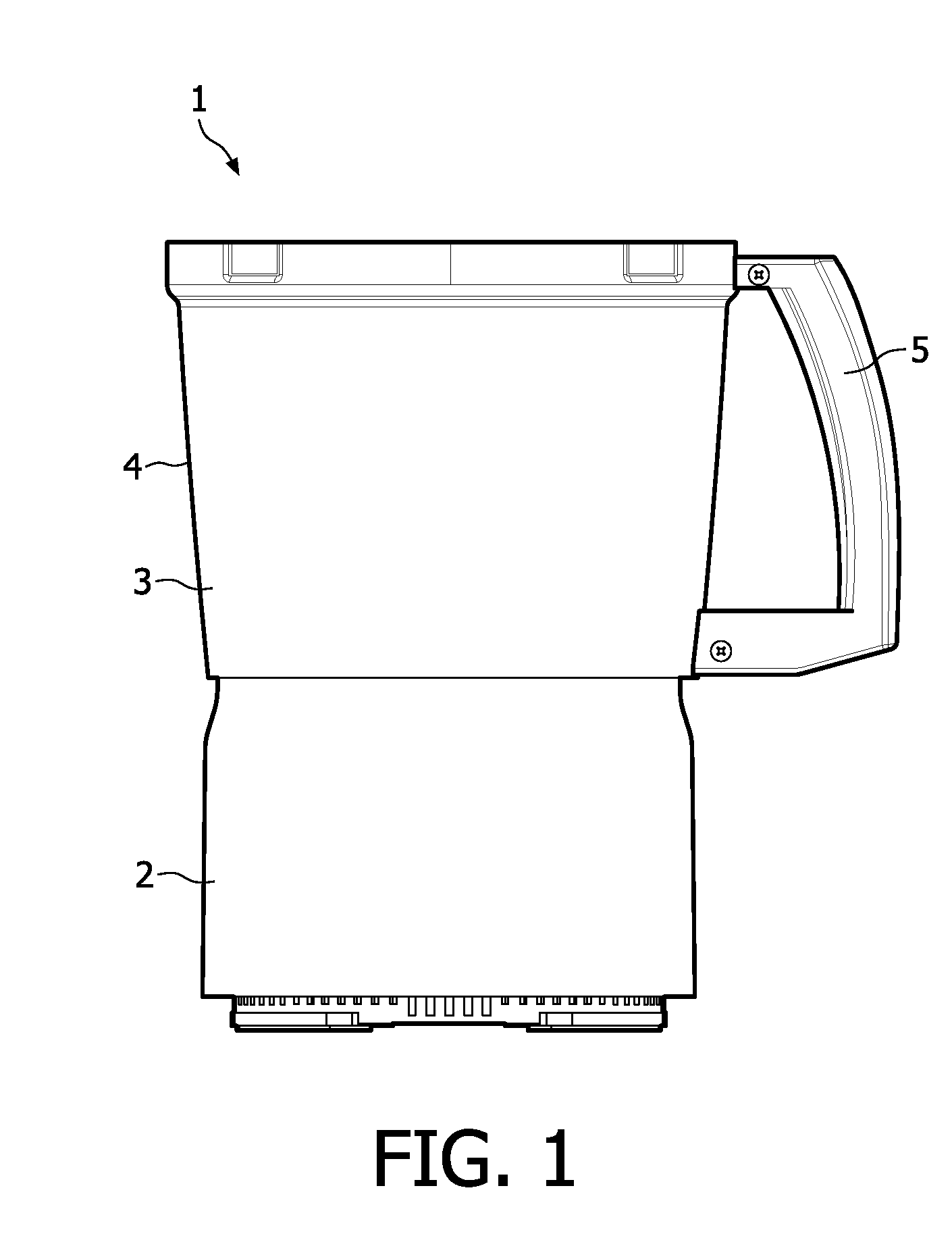
[0036]Referring to FIG. 1, there is shown a kitchen appliance, generally denoted by reference numeral 1. The kitchen appliance 1 is for example a food processor for preparing food stuffs, or is a mixer. The kitchen appliance 1 as shown in FIG. 1 comprises a base station 2, which encloses a drive means for driving a rotatable drive shaft (see FIG. 2). The drive means is for example an electric motor connected to the mains, or which takes its energy from a rechargeable battery for example. The base station 2 may further comprise control means, such as control switches etcetera. These are not shown.

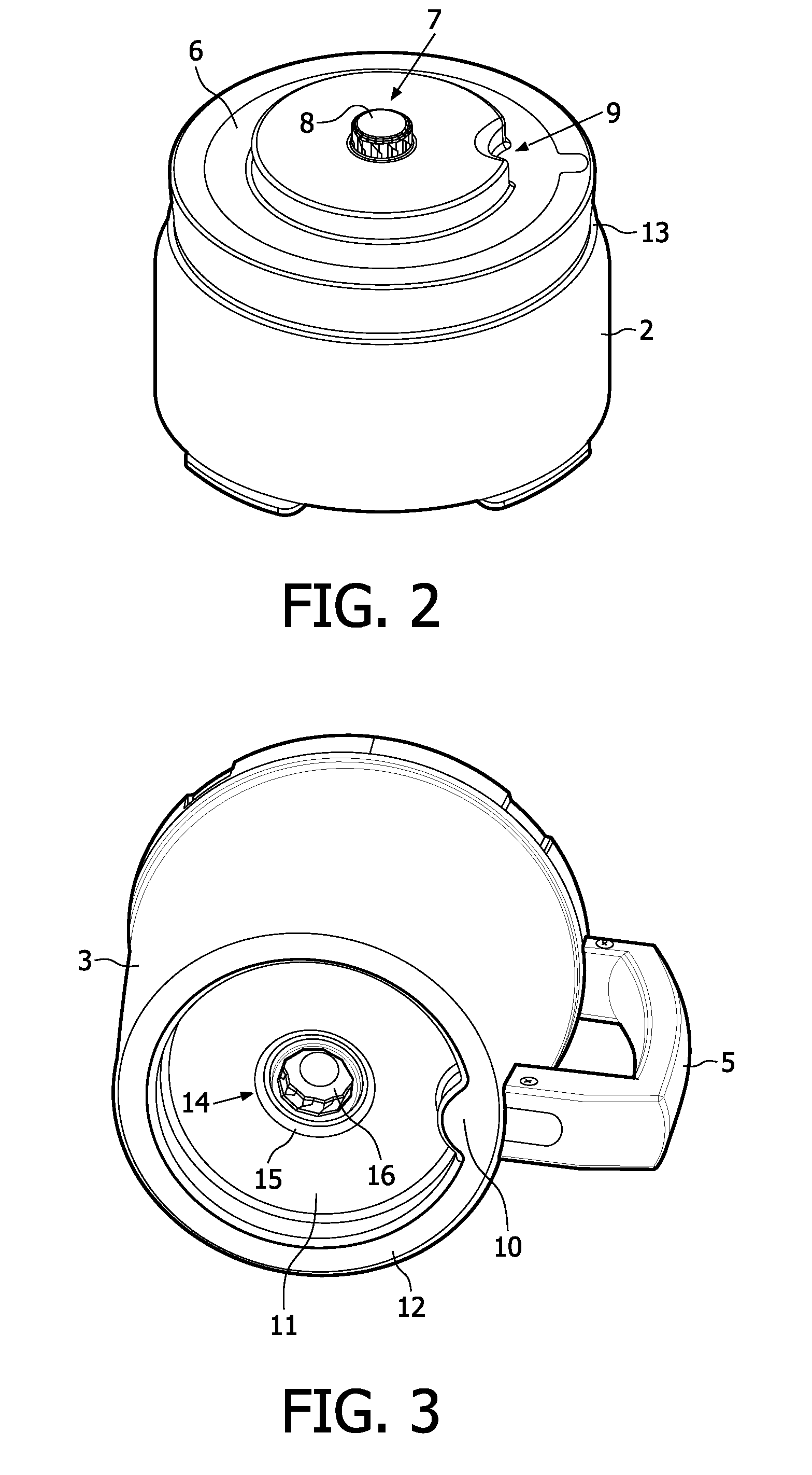
[0037]The kitchen appliance 1 further comprises a removable bowl 3, which has a bowl wall 4 and a bottom part 11 (see FIG. 3) and can hold food stuffs. The bowl further comprises a handle 5 so a person can handle the bowl, in particular can place the bowl 3 on the base station 2 and / or remove the bowl 3 from the base station 2.

[0038]FIG. 2 shows the base station 3 in a perspective view. The ...


PUM


Abstract

A kitchen appliance comprising a base station (2) having a support surface (6) on an upper portion thereof and a rotatable drive shaft comprising a first coupling part (7) at a free end thereof. The appliance comprises a removable bowl (3) comprising a bottom part that is supported by the support surface (6) during operation and a coupling member (14) supported from said bottom part. The member comprises a second coupling part (15) for coupling with the first coupling part (7). The first coupling part (7) comprises a head (8) with an outer surface (19) with a number of first cam portions (20). The second coupling part (15) comprises a socket (16) for accommodating the head (8), the socket has an inner circumferential surface (23) with a number of second cam portions (24), said first and second cam portions (20, 24) comprise first respectively second cam faces (21, 25), which mate upon accommodation of the head (8) in the socket (16).

Description

FIELD OF THE INVENTION[0001]The present invention relates to a kitchen appliance and to a tool for use with a kitchen appliance according to the present invention.BACKGROUND OF THE INVENTION[0002]Kitchen appliances such as food processors or stand mixers are well known in the prior art and are used in food preparation in general. In particular in professional food preparation environments ease of use and ease of workflow when using such kitchen appliances is required. In the case of kitchen appliances or food processors that comprise a removable bowl, ease of fixation of the bowl to a base station of the kitchen appliance is beneficial if the fixation itself does not require additional manual movement.[0003]Apart from the above, easy and secure fixation of tools used in such kitchen appliances is also paramount. From a hygienic point of view it is important that kitchen appliances and the parts thereof, such as bowls and tools, can be easily cleaned.[0004]U.S. Pat. No. 5,908,242 A d...

Claims


Application Information

Patent Timeline
IPC IPC(8): B02C23/00
CPCA47J43/0716A47J43/07F16D1/101
Inventor QUINESSER, ALBERT
Owner KONINKLIJKE PHILIPS ELECTRONICS NV
Why Eureka
Try Eureka