Venting system for a stove

Inactive Publication Date: 2011-03-31
AFIRE
View PDF1 Cites 0 Cited by
  • Summary
  • Abstract
  • Description
  • Claims
  • Application Information

AI Technical Summary

Benefits of technology

[0008]The main object of the present invention is to provide a venting system that controls the air flo

Problems solved by technology

Comparing to liquid or gaseous fuel, the burning

Method used


Image

  • Venting system for a stove
  • Venting system for a stove
  • Venting system for a stove

Examples


Embodiment Construction

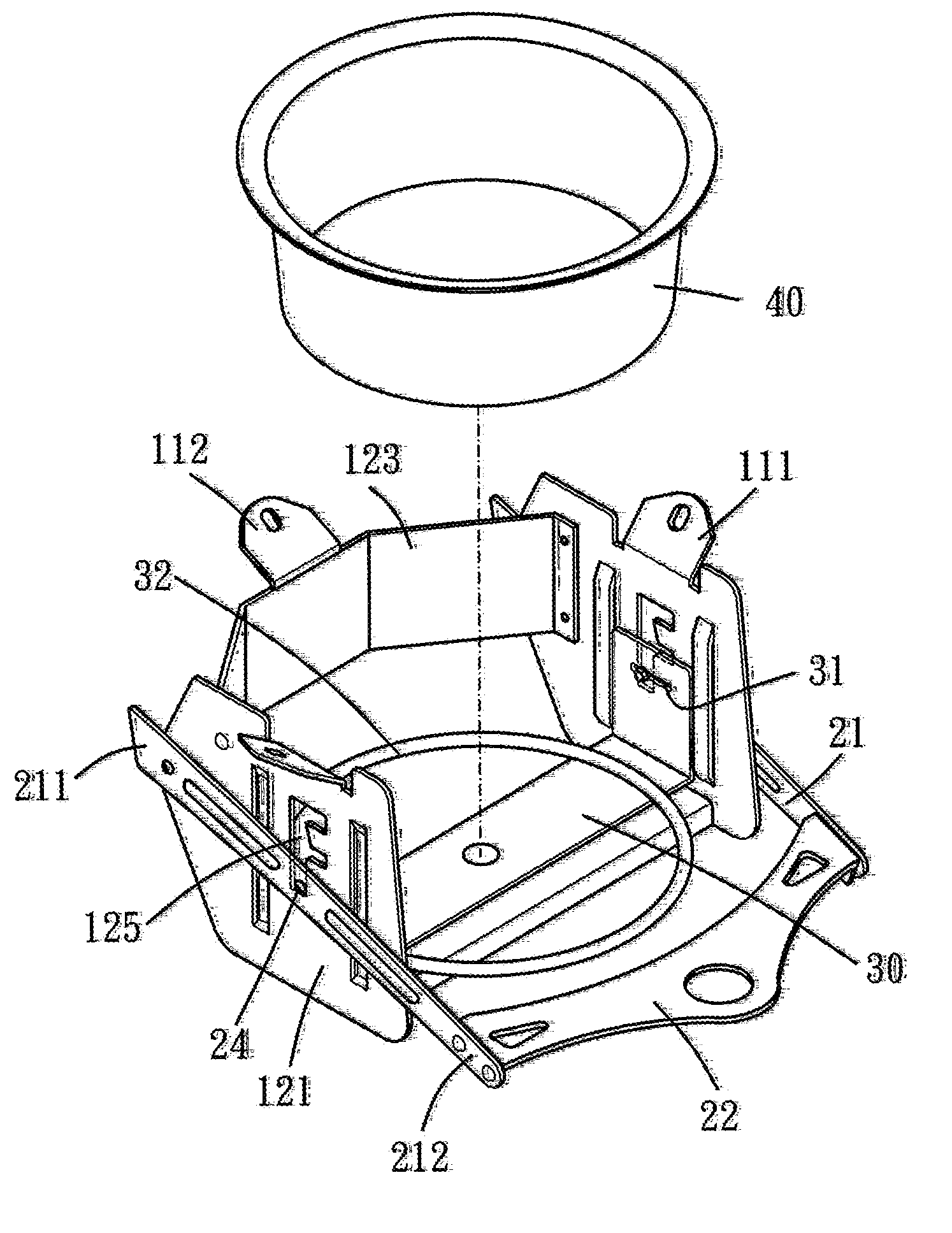
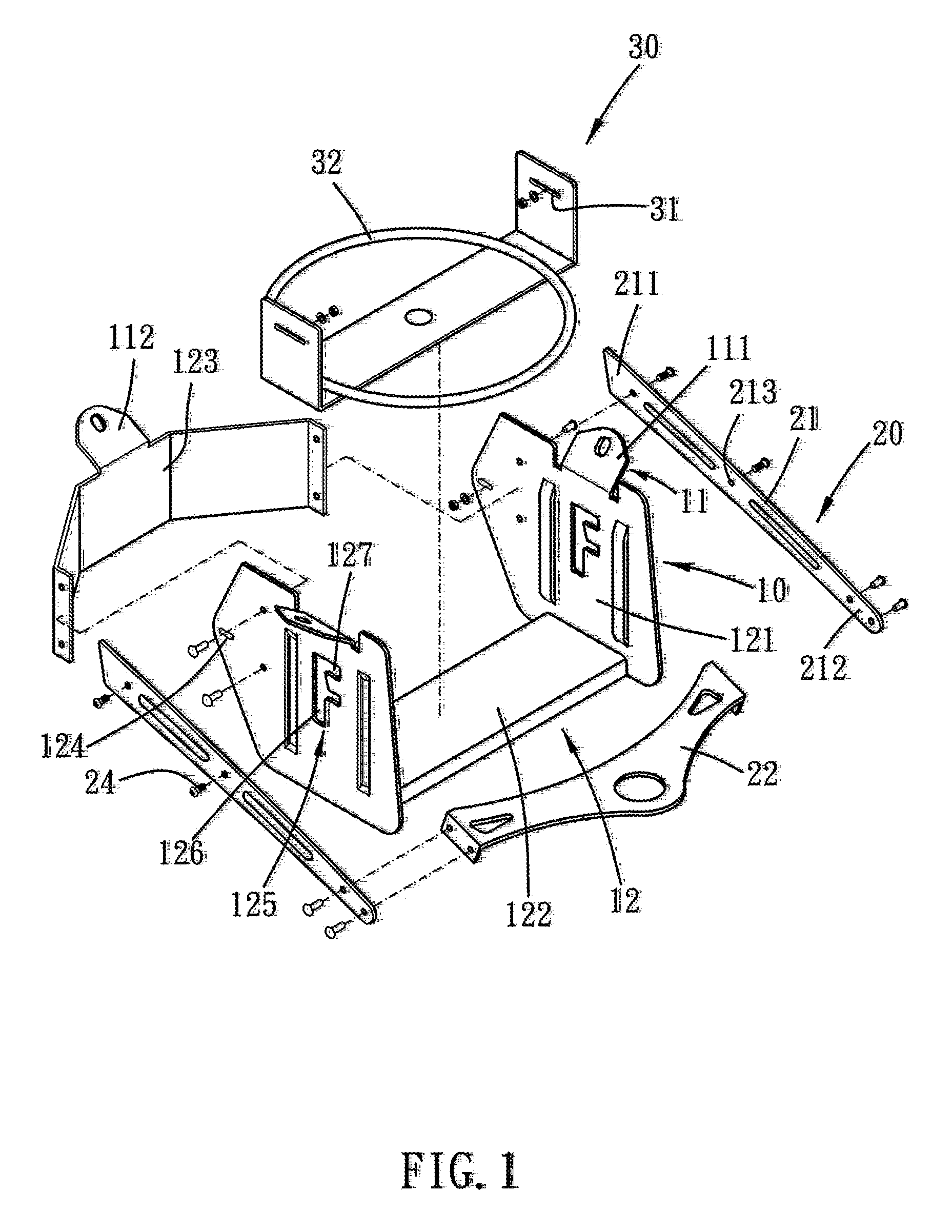
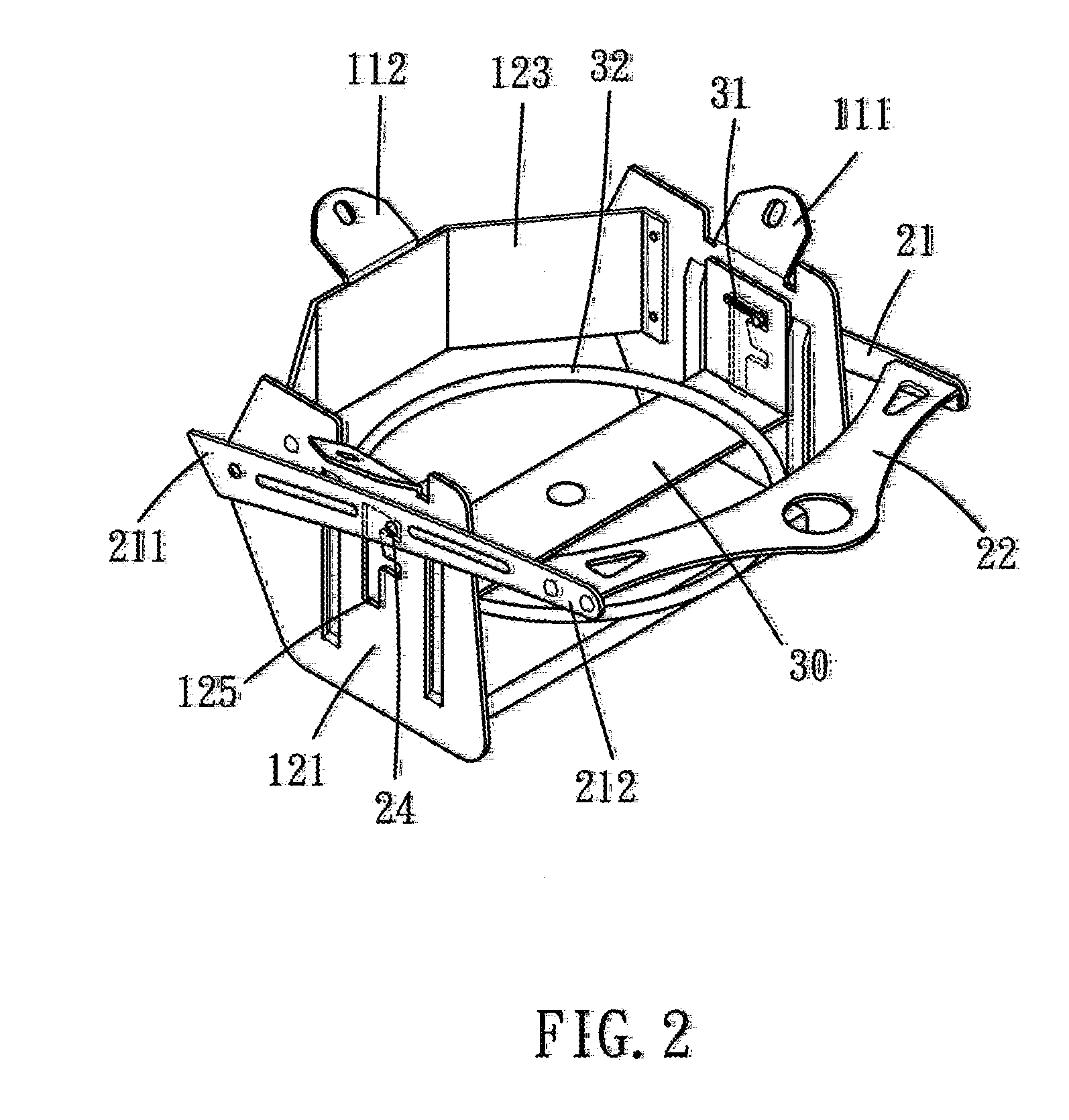
[0018]Please refer to FIG. 1 to FIG. 4 for a preferred embodiment of the present invention. A venting system, for a stove includes a main body 10, an adjuster 20 and an elevator 30. The venting system is disposed beneath the stove, which has a bottom opening disposed on a bottom thereof. The stove defines a burning room for solid fuel, such as charcoal, to burn therein, and at least a part of the air, i.e. the oxygen, needed to burn the charcoal flows into the burning room via the bottom opening. Whereby, heat generated by burning the charcoal can be used to cook food in a suitable manner such as roasting, stewing, frying, boiling or sauteing.

[0019]The main body 10 has a fixation portion 11 and a connecting portion 12. The fixation portion 11 is fixed to the bottom of the stove. Specifically, the connecting portion 112 includes two opposite connecting plates 121. A. bridge plate 122 bridges between bottom sides of the connecting plates 121, and a surrounding plate 123 bridges betwee...


PUM


Abstract

A venting system for a stove includes a screen disposed beneath a bottom opening of the stove and an elevation means for adjusting a height of the screen so as to enable the screen to selectively move close to or away from the bottom opening. More specifically, the elevation means includes a main body and an adjuster, and the screen includes an elevator. The main body has a fixation portion and a connecting portion. The fixation portion is fixed to a bottom of the stove, and the adjuster is movably connected to the connecting portion. The elevator and the adjuster are in a motional operative relationship. As such, the elevator can be elevated, by the adjuster to selectively move close to or away from the bottom opening.

Description

BACKGROUND OF THE INVENTION[0001]1. Field of the Invention[0002]The present invention relates to a venting system for a stove, and more particularly to a venting system disposed beneath the stove to control the air flow of a bottom opening of the stove.[0003]2. Description of the Prior Art[0004]Most of the conventional stoves for BBQ use solid fuel, such as charcoal, as a source for supplying a fire. Comparing to liquid or gaseous fuel, the burning rate of the solid feel is harder to be controlled. A common way to adjust the burning rate thereof is to control the air flow rate of the venting opening of the stove, so as to provide the stove with a desired heat.[0005]A conventional method to control the air flow rate is as disclosed, in U.S. Pat. No. 6,349,713, which provides an air supply window (7) and a door (7a) that selectively open or close the window (7) to adjust the air flow rate thereof.[0006]Another method to control the air flow rate is as, disclosed in U.S. Pat No. 4,416,...

Claims


Application Information

Patent Timeline
IPC IPC(8): A47J37/07
CPCA47J37/079
Inventor CHANG, FREDDIE
Owner AFIRE
Why Eureka
Try Eureka