Abradable coating system

Active Publication Date: 2011-05-05
ANSALDO ENERGIA SWITZERLAND AG
View PDF44 Cites 41 Cited by
  • Summary
  • Abstract
  • Description
  • Claims
  • Application Information

AI Technical Summary

Benefits of technology

[0083]The structure provided in the centimetre range along the x axis is beneficial in order to stabilize the whole coating. In addition in the x-y plane, it creates a labyrinth for the airflow, which reduces the air losses and may improve

Problems solved by technology

In the state-of-the-art, there are limitations in the design due to the materials and the processes used.
Indeed, for example none of the const

Method used


Image

  • Abradable coating system
  • Abradable coating system
  • Abradable coating system

Examples


second embodiment

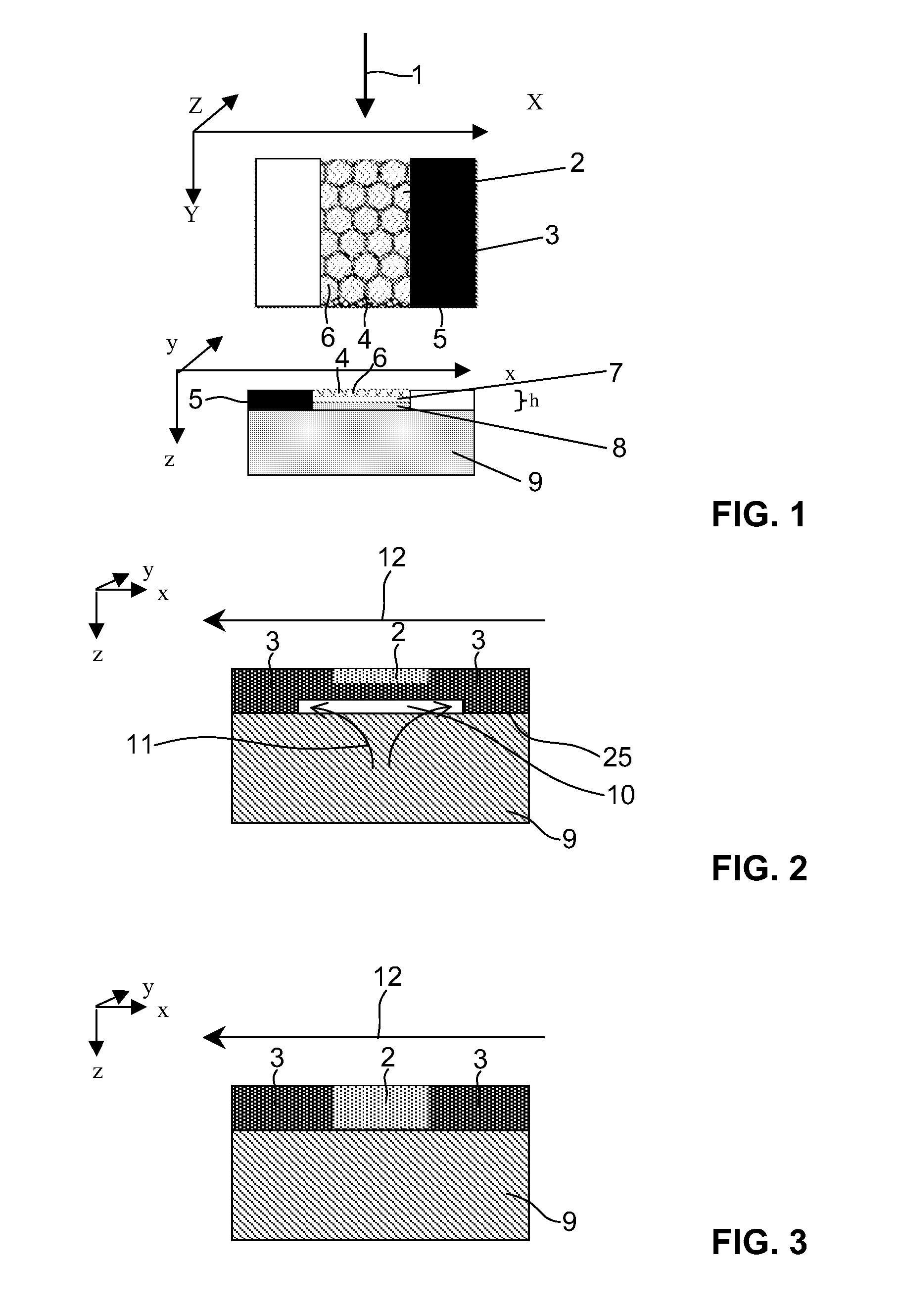
[0086]FIG. 2 with cooling channels shows an abradable coating system according to principles of the present invention. Again along the direction 12 of hot gas flow there are two side parts 3 and a central center part 2. Again the center part 2 is made of a tissue / matrix material combination with significantly higher abradability than the material of the surrounding part 3. Both parts, that is, the center part 2 as well as side parts 3, can be made based on a tissue material with a matrix.

[0087]In this case, in order to allow efficient cooling, the abradable sealing system is provided with a groove or channel like structure 10 which, as the system is mounted on substrate 9, allows the flow through of cooling medium such as cooling air 11. In this case there is provided one single cooling channel, it is however also possible to have a row of parallel cooling channels, which may be arranged in a circumferential or in a axial direction or in a combination thereof, and is also possible t...

third embodiment

[0088]FIG. 3 shows a third embodiment with an erosion resistant coating on the side 3 and a more easily abradable coating in the middle part 2 in the plane x-y. The coating can be realized in one block (monoblock) by impregnation with different matrix materials according to the embodiment of FIG. 8, or by using differing degrees of impregnation. It can be realized also with three separated different blocks or patches according to the embodiment of FIG. 10. In this case, the central part 2 is formed as a block of the same height in the z direction as the side parts 3.

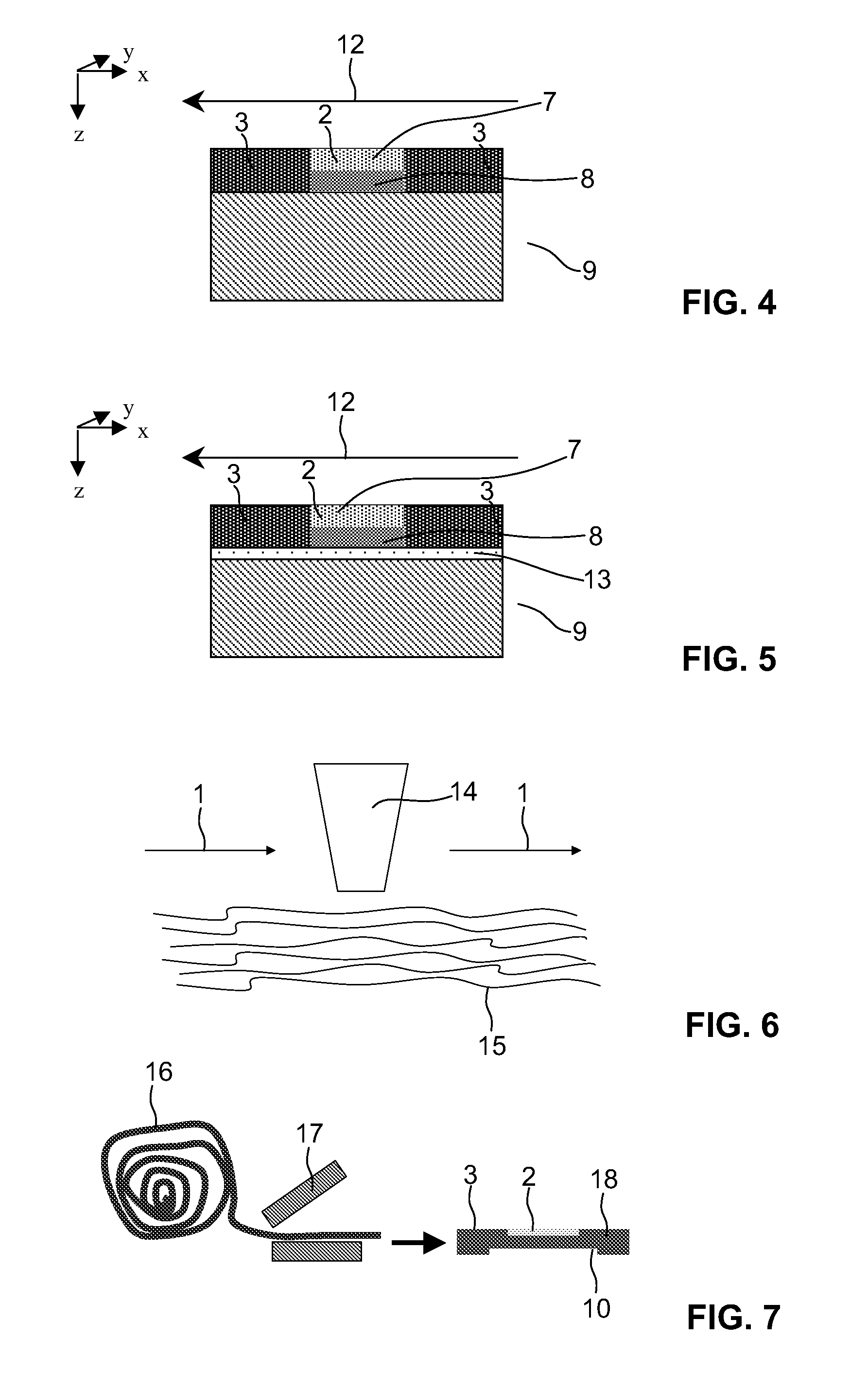
[0089]Yet another embodiment is schematically illustrated in FIG. 4. This embodiment is provided with a different porosity and / or erosion resistance along z and in the plane x-y. The coating can be realized in one block (monoblock) by impregnation of different matrix materials according to the embodiment of FIG. 8. It can also be realized in four different blocks according to the embodiment of FIG. 10. In this case, ther...


PUM

PropertyMeasurementUnit
Heightaaaaaaaaaa
Fractionaaaaaaaaaa
Electrical resistanceaaaaaaaaaa

Abstract

An abradable coating system (2-8) for a turbine or a compressor is proposed has at least one layer of woven or non-woven tissue (15) or foam made of: ceramic, glass, glass-ceramic, ceramic-metal composite and combinations thereof. A free-standing preformed element (18) has at least one layer of such a woven or non-woven tissue or foam is filled with fillers and/or binder. A method prepares such a system. Finally, a method for the repair of an abradable coating portion of a turbine or the compressor component (9) includes in a first optional step that the damaged portion is at least partly removed and/or cleaned and/or surface treated, and in a second step at least one free-standing preformed abradable coating element (18) or a complete abradable coating system is attached to the component (9), preferably by using a matrix, wherein for example only a center part (2) or a fraction of a center part (2) is replaced.

Description

[0001]This application claims priority under 35 U.S.C. §119 to U.S. Provisional application no. No. 61 / 256,393, filed 30 Oct. 2009, the entirety of which is incorporated by reference herein.BACKGROUND[0002]1. Field Of Endeavor[0003]The present invention relates to an abradable coating system, a free-standing preformed element therefor, as well as to methods for making such system / preformed elements, and to turbine and compressor components having such structures, and to a repair scheme.[0004]2. Brief Description of the Related Art[0005]Compressors and turbines of gas and steam turbine engines are provided with abradable coatings at several positions. Abradable coatings are, for example, provided on the radial inner surfaces of compressor and / or turbine stator components.[0006]Abradable coatings in this context are, e.g., known from: EP 1 392 957; EP 1 734 146; EP 1 975 271; EP 1 273 675; WO 03 / 010419; U.S. Patent Application Publication No. 2005 / 0123785; U.S. Patent Application Publ...

Claims


Application Information

Patent Timeline
IPC IPC(8): F01D11/12B32B37/16
CPCF01D5/284F01D11/122F01D11/125Y02T50/67Y02T50/672F05D2300/615F05D2300/21F05D2300/6012F05D2230/90F05D2300/603F05D2300/612F01D5/005Y02T50/60
Inventor DUVAL, SOPHIEGRASSO, PIERO-DANIELEOLLIGES, SVENFERBER, JOERGENSTANKOWSKI, ALEXANDER
Owner ANSALDO ENERGIA SWITZERLAND AG
Why Eureka
Try Eureka