Alternating circumferential bridge stent design and methods for use thereof

a technology of circumferential bridge and stent, applied in the field of stents, can solve problems such as difficult to solve with a single design

Active Publication Date: 2011-05-05
CONFLUENT MEDICAL TECH INC
View PDF107 Cites 49 Cited by
  • Summary
  • Abstract
  • Description
  • Claims
  • Application Information

AI Technical Summary

Benefits of technology

[0006]In general, in one aspect, a stent includes a first section and a second section aligned with the first section along a longitudinal axis of the stent. The first section and the second section each include a plurality of expandable modules and a plurality of bridging modules. Each expandable module includes a plurality of strut elements that join togeth

Problems solved by technology

These competing demands have proven dif

Method used


Image

  • Alternating circumferential bridge stent design and methods for use thereof
  • Alternating circumferential bridge stent design and methods for use thereof
  • Alternating circumferential bridge stent design and methods for use thereof

Examples


examples

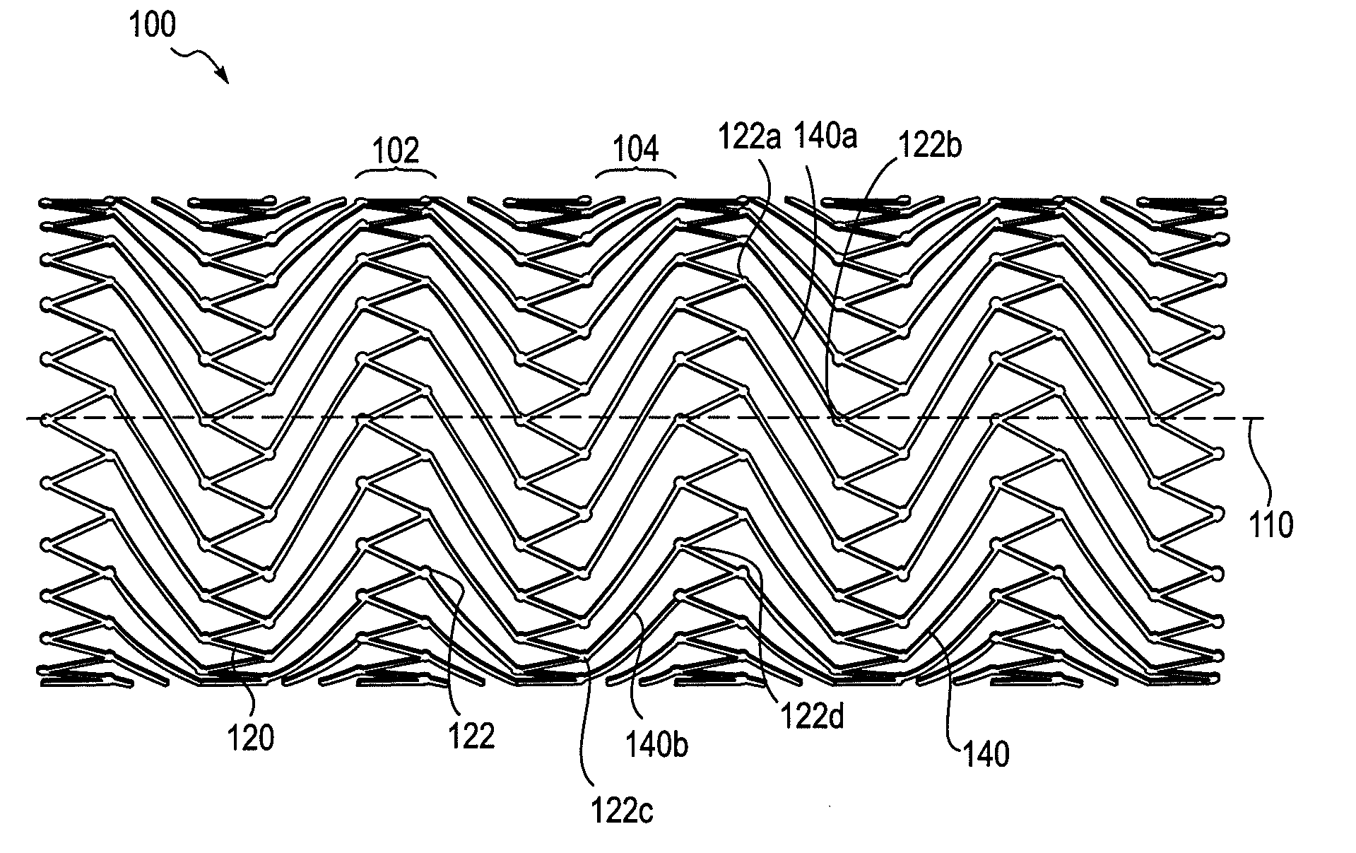
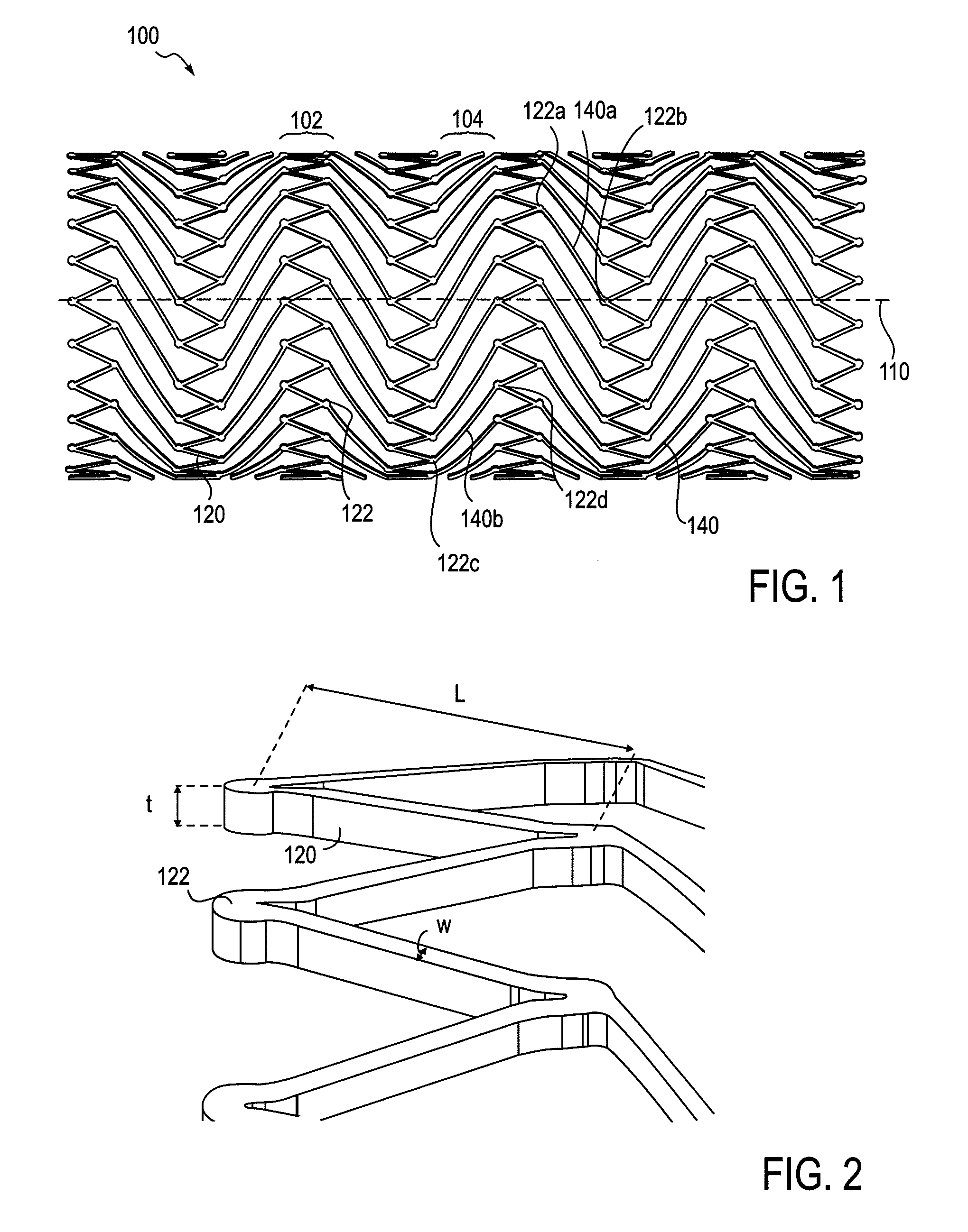
[0071]As an extreme example, consider holding the length l constant and varying the angle θ in a hypothetical series of different designs. In a first design, referring to FIG. 6A, as the angle θ approaches 0°, the bridging elements 140 approach an orientation parallel to the longitudinal axis of the stent. At this extreme, the bridging elements 140 have virtually no contribution to the radial strength of the stent. As the stent expands or contracts, assuming that the bridging elements 140 maintain their horizontal orientation, there is zero relative rotation between adjacent expandable ring members. Further, these horizontally oriented bridging elements inhibit bending flexibility.

[0072]In a second design, referring to FIG. 6B, as the angle θ approaches 90°, the bridging elements 601 approach a circumferential orientation. At this extreme, the bridging elements 601 have a significant contribution to the radial strength of the stent. Moreover, as the stent expands or contracts, the r...


PUM


Abstract

A stent includes a first section and a second section. The first section and the second section each include a plurality of expandable modules and a plurality of bridging modules. Each expandable module includes a plurality of strut elements that join together at a plurality of apices, and each bridging module includes bridging elements that connect an apex of a first module with an apex of a second module. In some aspects, the first section is more flexible along the longitudinal axis of the stent than the second section and is configured to be placed in a specific region of a vessel that requires flexibility to accommodate surrounding anatomy. In some aspects, the first section is more radially stiff than the second section and is configured to be placed in a specific region of the vessel that requires radial stiffness to counteract crushing force caused by surrounding anatomy.

Description

CROSS REFERENCE TO RELATED APPLICATIONS[0001]This application claims priority to U.S. Provisional Patent Application No. 61 / 258,145, filed Nov. 4, 2009 entitled “Stent for Relief of Pelvic Venous Outflow Obstruction and Methods for Use Thereof.” This application also claims priority to U.S. Provisional Patent Application No. 61 / 290,836, filed on Dec. 29, 2009 entitled “Alternating Circumferential Bridge Stent Design and Methods of Use Therefore.” This application also claims priority to U.S. Provisional Patent Application No. 61 / 391,462, filed on Oct. 8, 2010 entitled “Alternative Circumferential Bridge Stent Design and methods of Use Therefore.” These applications are herein incorporated by reference in their entirety.INCORPORATION BY REFERENCE[0002]All publications and patent applications mentioned in this specification are herein incorporated by reference to the same extent as if each individual publication or patent application was specifically and individually indicated to be i...

Claims


Application Information

Patent Timeline
IPC IPC(8): A61F2/82
CPCA61F2230/0054A61F2/91A61F2250/0018A61F2250/0019A61F2250/0036A61F2002/046A61F2002/91541A61F2002/91575A61M1/3655A61F2/915
Inventor BONSIGNORE, CRAIGKLESHINSKI, STEPHEN J.
Owner CONFLUENT MEDICAL TECH INC
Why Eureka
Try Eureka