Muntin clip

a technology of muntin bars and clips, which is applied in the field of window units, can solve the problems of increasing the likelihood of securing the muntin bars into permanent position, and reducing the likelihood of breaking or cracking

Inactive Publication Date: 2011-06-09
S I L PLASTIC SALES & SUPPLIES
View PDF19 Cites 7 Cited by
  • Summary
  • Abstract
  • Description
  • Claims
  • Application Information

AI Technical Summary

Benefits of technology

[0013]The tongue may comprise an arm extending orthogonally from the base, and a plurality of resiliently flexible wings extending outwardly from the arm and frictionally engaging the muntin. The arm may comprise a foot adjacent the base, a body portion extending from the foot, and a distal end portion adjacent the body portion. The plurality of wings may extend from body portion, and may be angled towards the foot. The arm may be generally rectangular in transverse cross section, and the plurality of wings may comprise a first set of wings extending from a first side of the arm and a second set of wings extending from an opposed second side of the arm. The distal end portion may comprise a bevel. The foot may frictionally engage the muntin. The body portion may have a cross sectional area less than the cross sectional area of the foot. The tongue may be spaced from the first end and the second end of the base.
[0014]According to another aspect, a window glazing unit is provided. The window glazing unit comprises a first glazing pane and a second glazing pane in parallel and opposed relation to the first glazing pane. The first and second glazing panes are spaced apart by a glazing gap. A seal is disposed between the first and second glazing panes about the periphery thereof. The seal has a seal height equal to the glazing gap and a seal width transverse to the seal height. At least one generally hollow muntin is provided between the first glazing pane and the second glazing pane. The muntin has at least one end adjacent the seal. A muntin clip secures the end of the muntin in a fixed position to the seal. The muntin clip comprises a base having an interior face and an opposed exterior face. The interior and exterior faces extend between a base first end positioned towards the first glazing pane and a base second end positioned towards the second glazing pane. A muntin connector extends from the interior face. The muntin connector comprises a tongue received within the end of the muntin and frictionally secured therein. A seal connector extends from the exterior face. The seal connector comprises a side plate positioned between the seal and the first glazing pane. The side plate has an inner face facing the seal and an opposed outer face. The inner face and the outer face extend between a side plate first end adjacent the base and an opposed side plate second end, and define a side plate width between the side plate first end and the side plate second end. The side plate width is substantially equal to the seal width. At least one tooth extends from the inner face and inserted into the seal.

Problems solved by technology

The apparatus lessens the likelihood of either breaking or cracking the glass panes, as multi-pane sealed unit assembly occurs, or of causing seal failure of such units either during manufacture or following installation and increases the likelihood of securing the muntin bars into permanent position.

Method used


Image

  • Muntin clip
  • Muntin clip
  • Muntin clip

Examples


Embodiment Construction

[0022]Various apparatuses or methods will be described below to provide an example of each claimed invention. No example described below limits any claimed invention and any claimed invention may cover processes or apparatuses that are not described below. The claimed inventions are not limited to apparatuses or processes having all of the features of any one apparatus or process described below or to features common to multiple or all of the apparatuses described below. It is possible that an apparatus or process described below is not an example of any claimed invention. Applicant reserves the right to claim such apparatuses or processes in other applications.

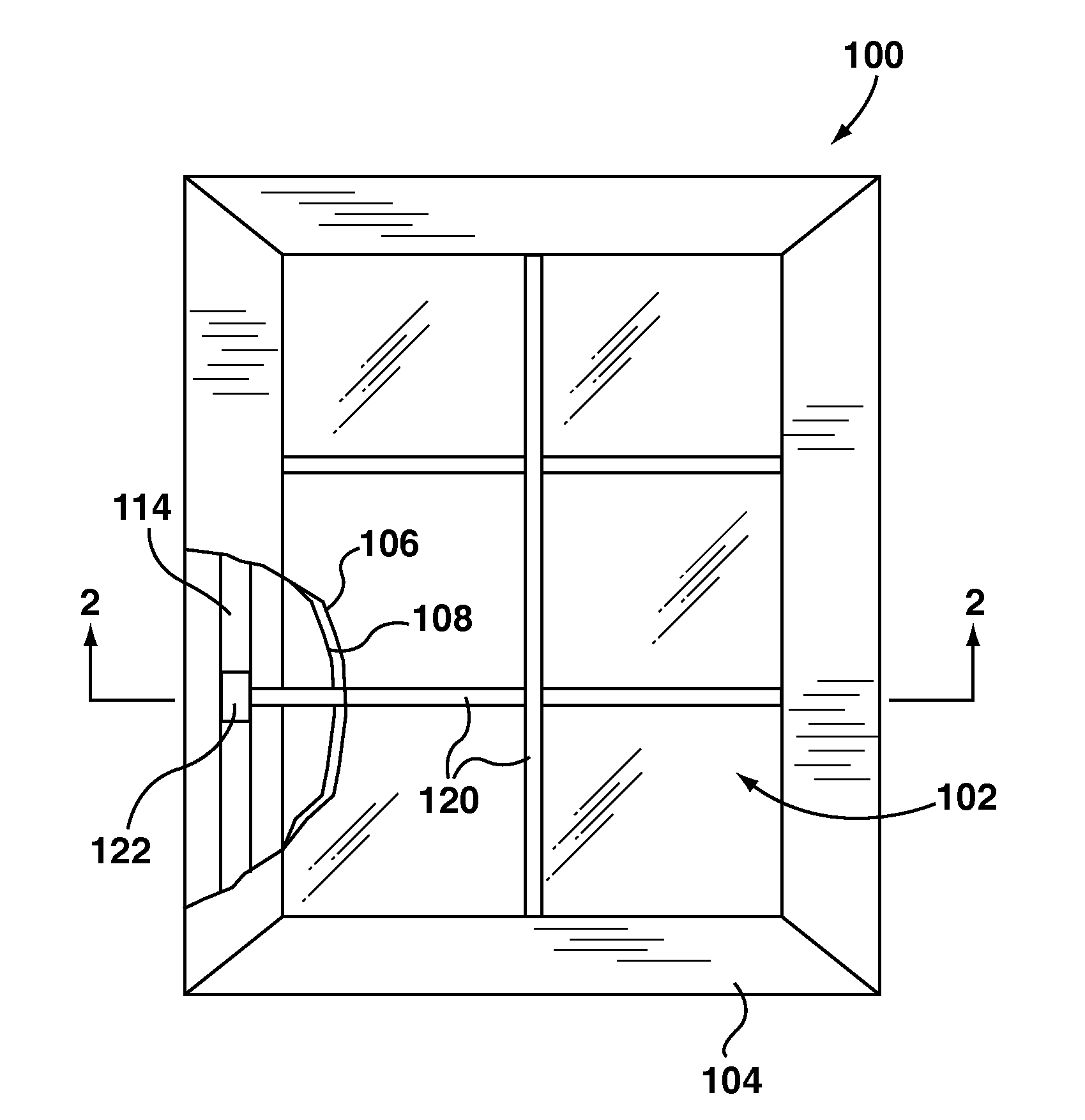
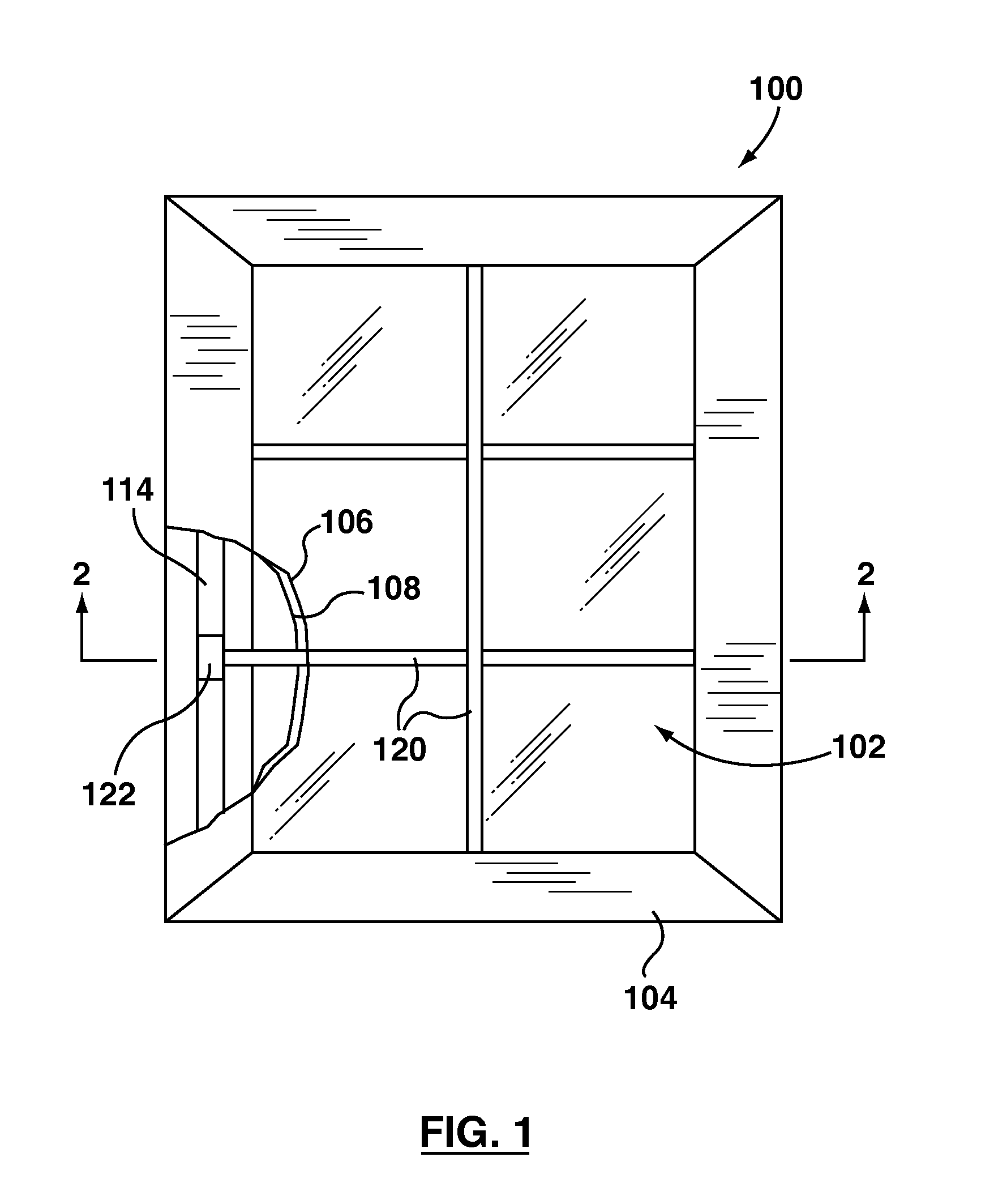
[0023]Referring to FIG. 1, an example of a window 100 is shown. The window 100 comprises a glazing unit 102, mounted in a window frame 104. The window frame 104 may be any suitable window frame, and may comprise a glass stop, which secures the glazing unit 102 to the frame.

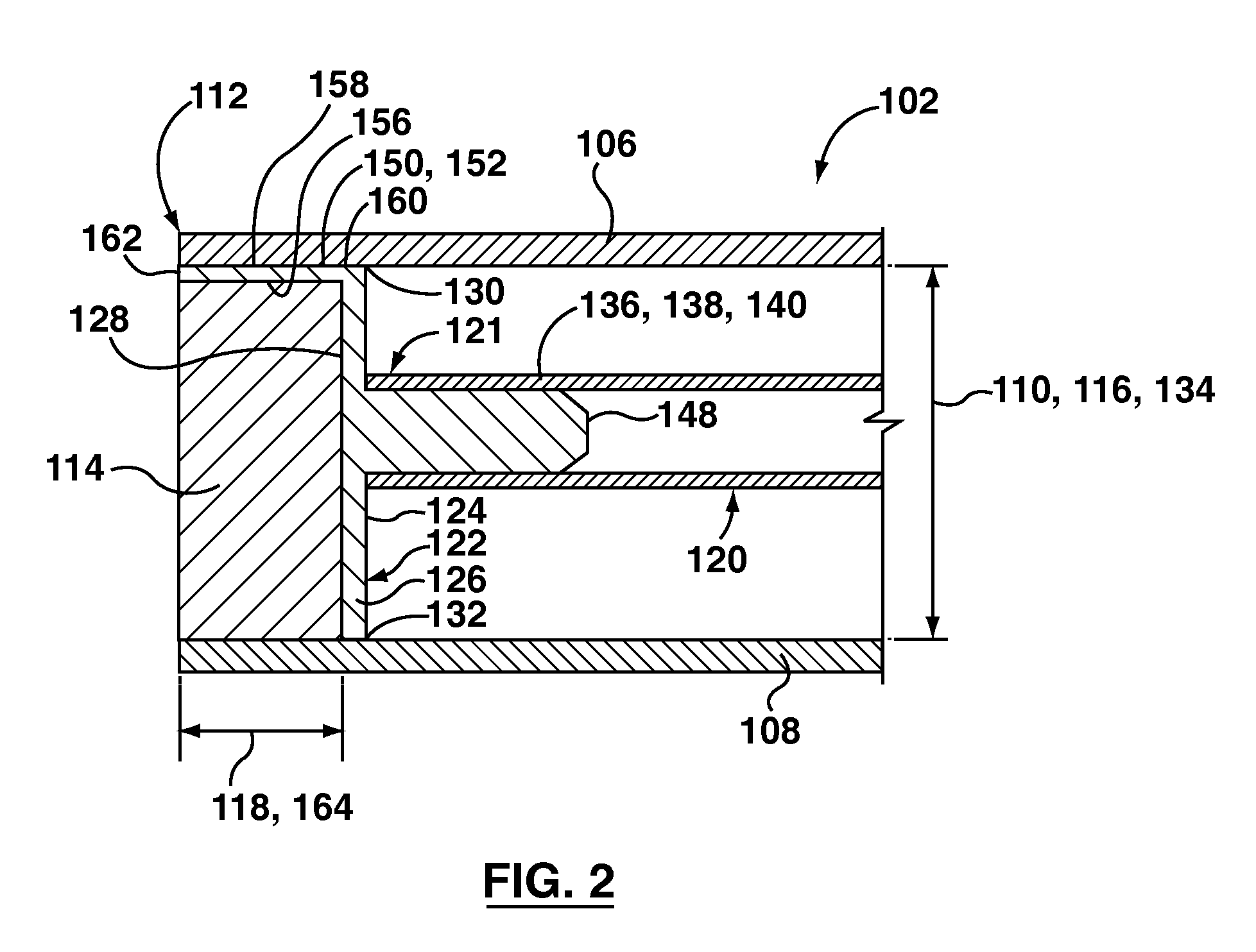
[0024]Referring to FIG. 2, the glazing unit 102 compr...


PUM


Abstract

A muntin clip comprises a base having an interior face and an opposed exterior face. The interior and exterior faces extend between a first end positionable towards the first glazing pane and a second end positionable towards the second glazing pane. A muntin connector extends from the interior face. The muntin connector comprises a tongue receivable within the muntin bar and frictionally securable therein. A seal connector extends from the exterior face. The seal connector comprises a side plate positionable between the seal and the first glazing pane. The side plate has an inner face positionable to face the seal and an opposed outer face. At least one tooth extends from the inner face. The at least one tooth is insertable into the seal.

Description

[0001]This application claims the benefit of Provisional Application No. 61 / 261,968, filed Nov. 17, 2009, which is hereby incorporated herein by reference.FIELD[0002]The disclosure relates to window units, and more particularly, to one or more methods or apparatuses associated with securing a muntin between first and second glazing panes of a window glazing unit.INTRODUCTION[0003]U.S. Pat. No. 7,568,317 (Longden) discloses a glazing clip for fitting about the edge of a glazing unit. The glazing clip comprises means for interengaging with an ancillary element on at least one side of a glazing unit, in use.[0004]U.S. Pat. No. 7,533,507 (Hornung et al.) discloses techniques for mounting simulated muntin bars, preassembled muntin grids and the like between parallel glazing sheets in an integrated multipane window sash. Among the mounting techniques disclosed are clips for holding simulated muntin components to a spacing and mounting structure of an integrated multipane window sash. Clip...

Claims


Application Information

Patent Timeline
Patent Type & Authority Applications(United States)
IPC IPC(8): E06B3/54
CPCE06B3/6675
Inventor IFKO, STEFAN
Owner S I L PLASTIC SALES & SUPPLIES
Why Eureka
Try Eureka