

Controller for a Power Converter
- Summary
- Abstract
- Description
- Claims
- Application Information
AI Technical Summary
Benefits of technology
Problems solved by technology
Method used
Image

Examples
Embodiment Construction
[0015]The making and using of the present exemplary embodiments are discussed in detail below. It should be appreciated, however, that the present invention provides many applicable inventive concepts that can be embodied in a wide variety of specific contexts. The specific embodiments discussed are merely illustrative of specific ways to make and use the invention, and do not limit the scope of the invention.
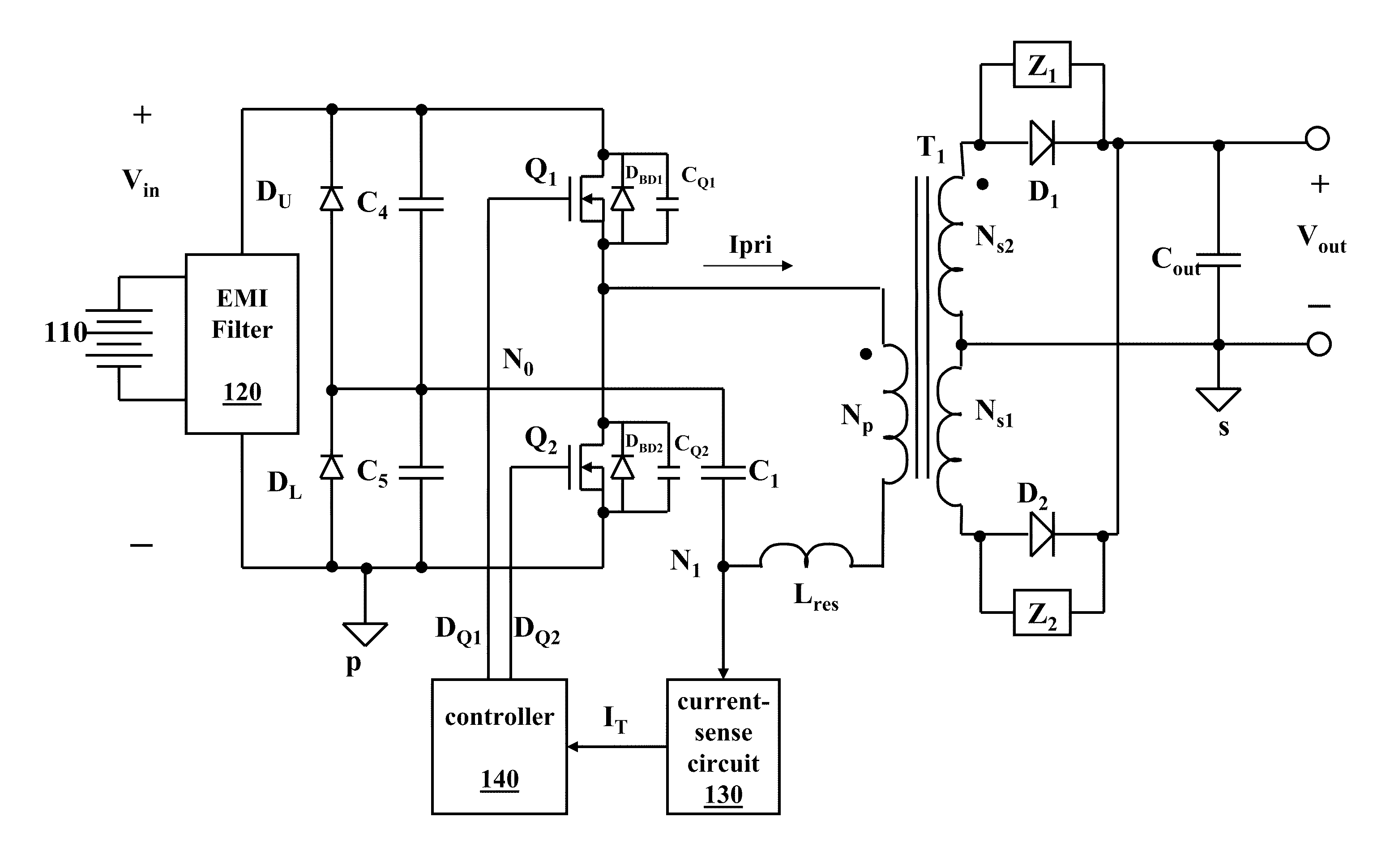
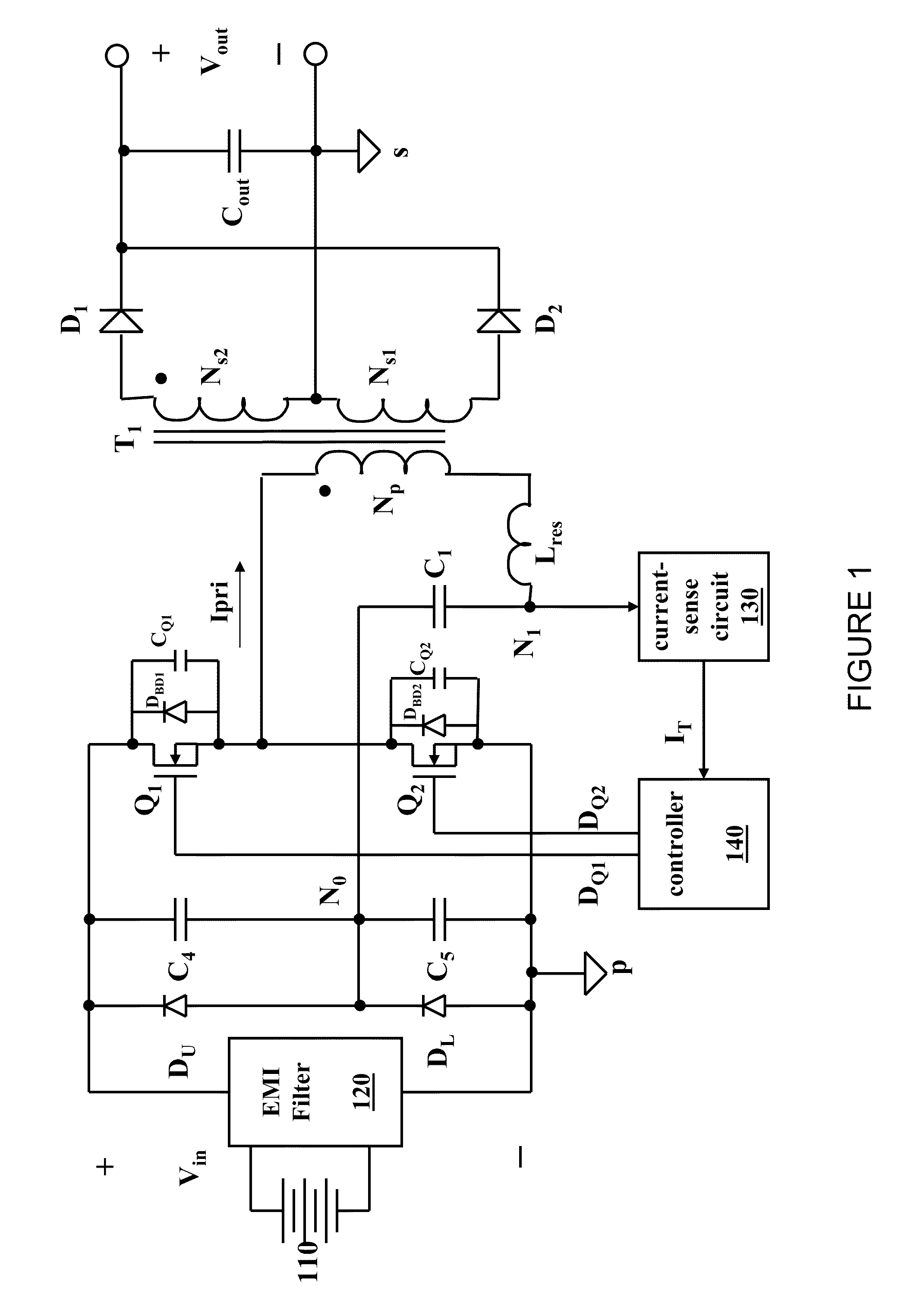
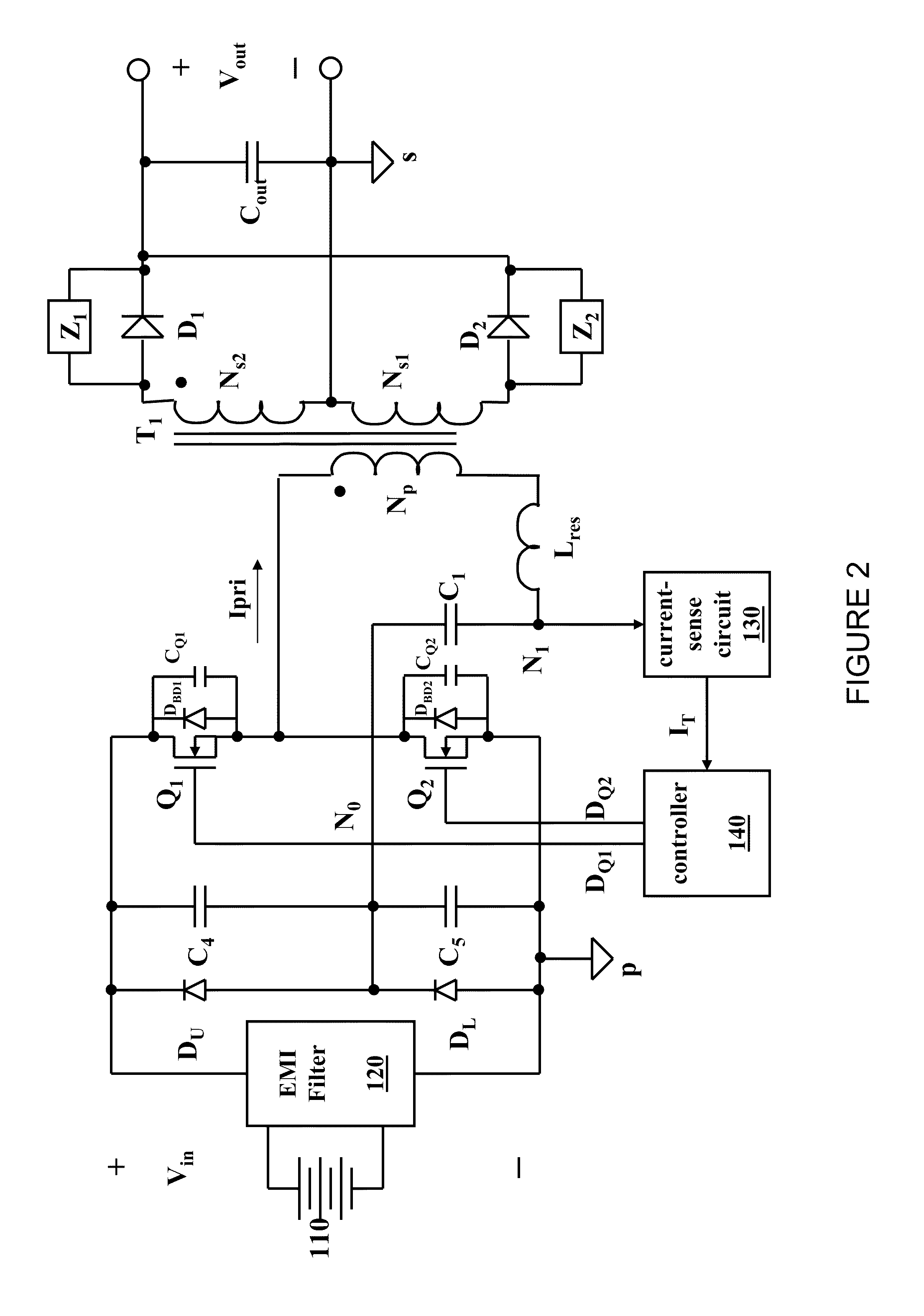
[0016]The present invention will be described with respect to exemplary embodiments in a specific context, namely, a power converter configured to provide reduced power dissipation at no load or at light load. While the principles of the present invention will be described in the environment of a power converter, any application that may benefit from a power converter with reduced power dissipation including a bias supply, a power amplifier, or a motor controller is well within the broad scope of the present invention.
[0017]A resonant full-bridge or half-bridge power converter,...
PUM
 Abstract
Description
Claims
Application Information