

Lens barrel and imaging apparatus
- Summary
- Abstract
- Description
- Claims
- Application Information
AI Technical Summary
Benefits of technology
Problems solved by technology
Method used
Image

Examples
first embodiment
1. First Embodiment
1-1. Configuration of Lens Barrel
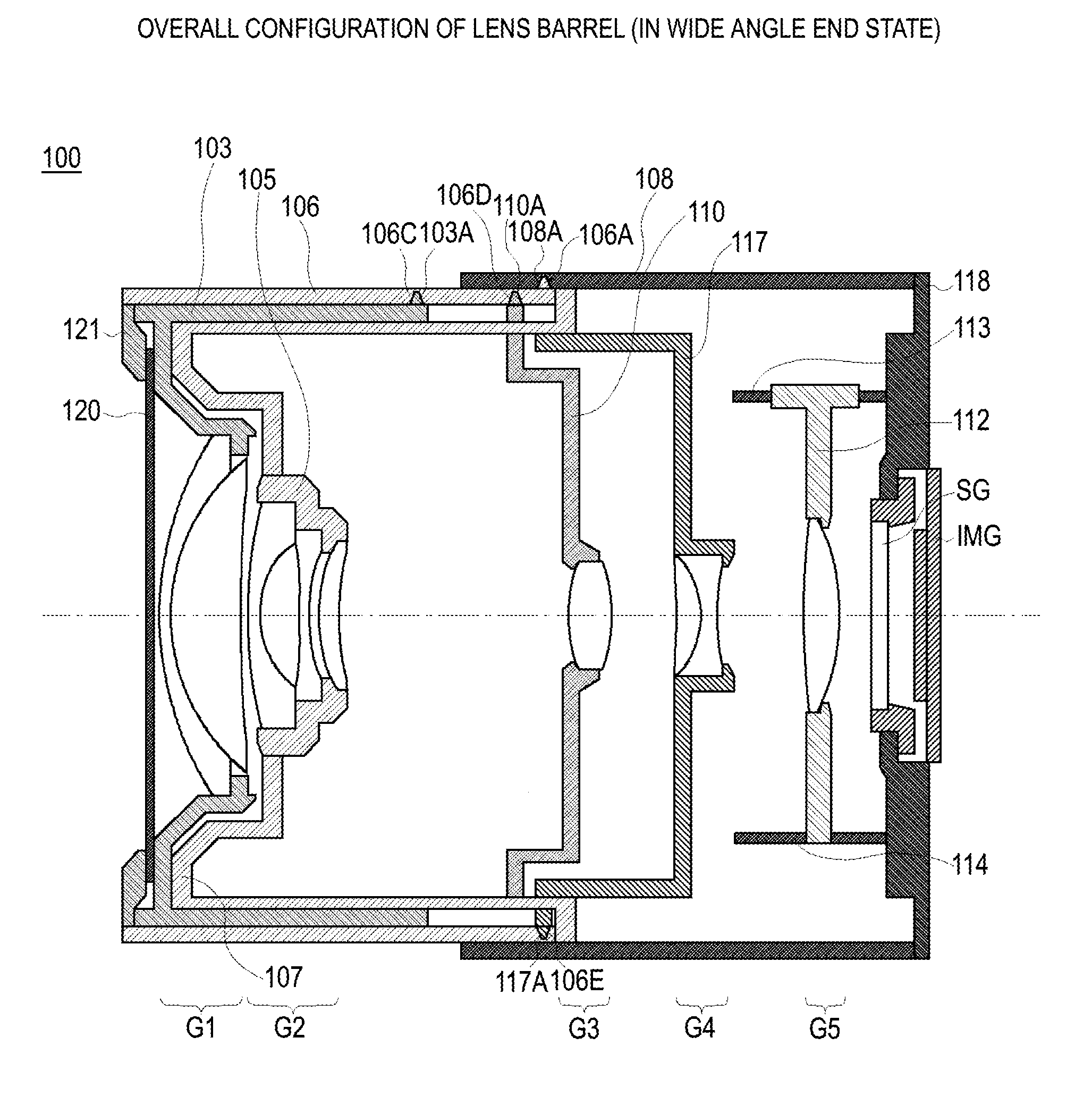
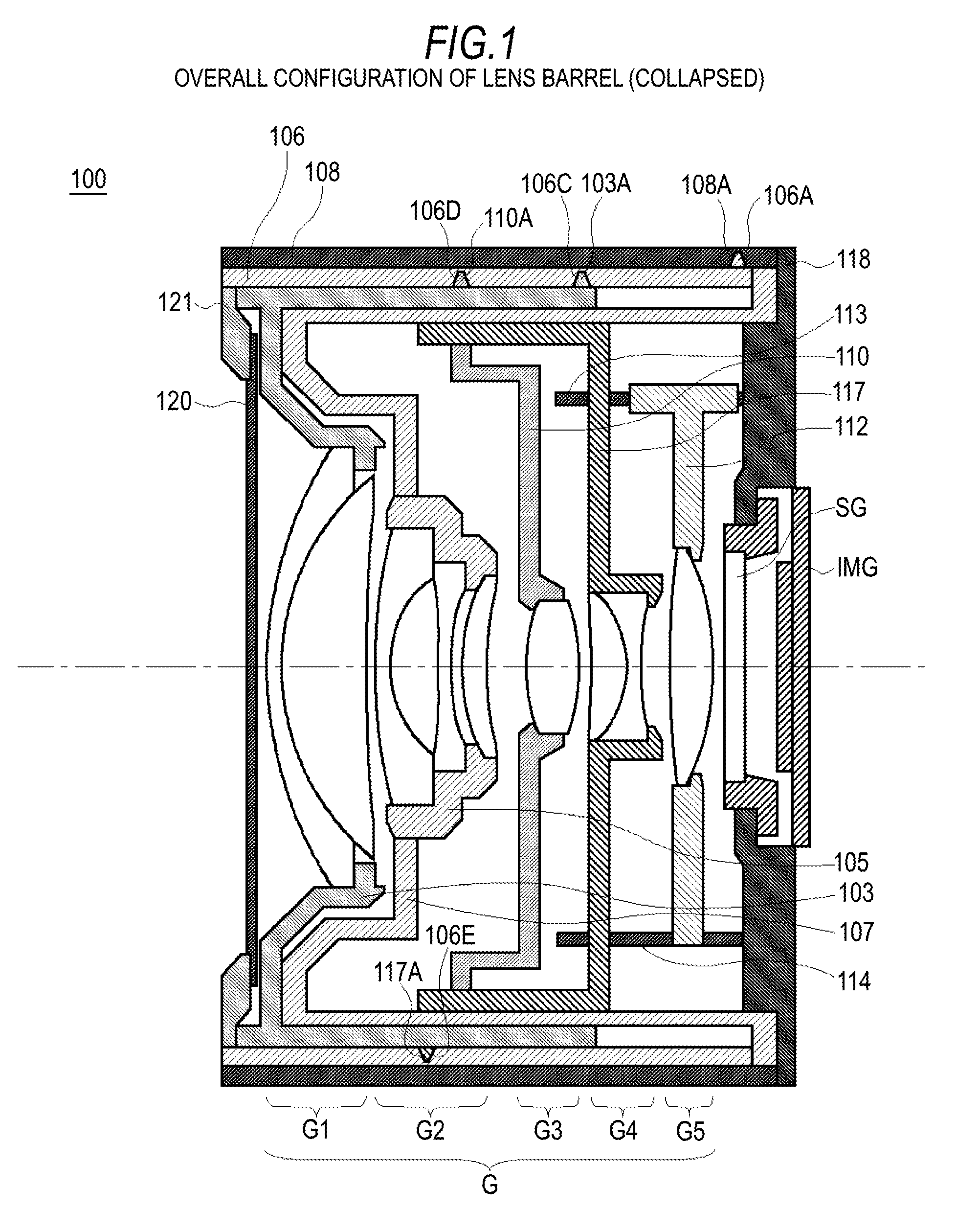
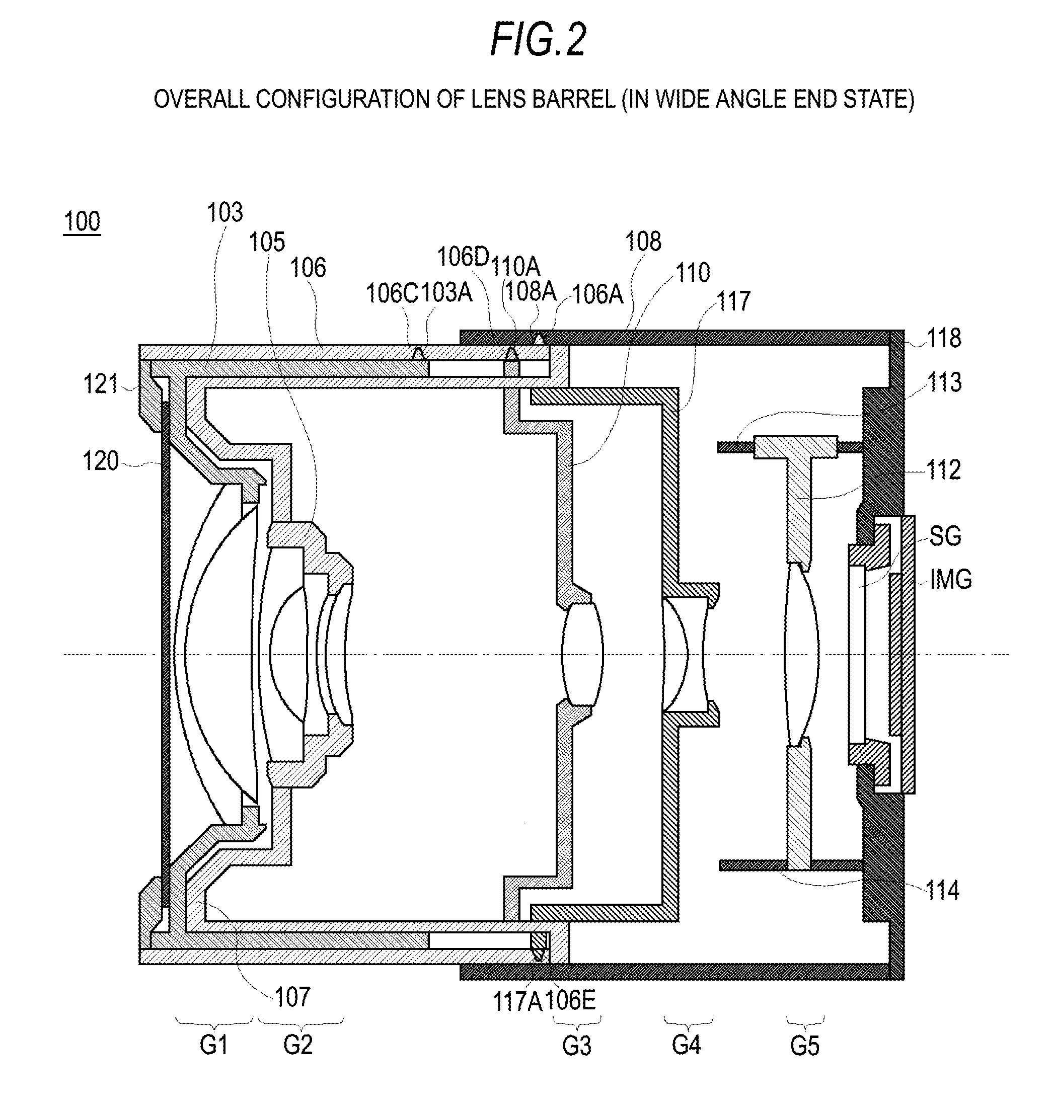
[0070]A lens barrel in a first embodiment includes a variable focal length lens system having at least three movable lens groups and a drive mechanism as guiding means for moving each of the movable lens groups that form the variable focal length lens system forward and backward in the optical axis direction.
[0071]In the following description, a lens system whose focus point where an image is brought into focus changes with the focal length is called a variable focal length lens system. On the other hand, being a lens system whose focus point does not change with the focal length, a zoom lens is considered as one type of variable focal length lens system.
[0072]A description will first be made of the configuration of the variable focal length lens system in the first embodiment. The variable focal length lens system in the first embodiment is formed of five lens groups, a first lens group having positive refracting power, a second l...
second embodiment
3. Second Embodiment
3-1. Configuration of Lens Barrel
[0204]A lens barrel in a second embodiment also includes a variable focal length lens system having at least three movable lens groups and a drive mechanism as guiding means for moving each of the lens groups that form the variable focal length lens system forward and backward in the optical axis direction.
[0205]A description will first be made of the configuration of the variable focal length lens system in the second embodiment. The variable focal length lens system is formed of five lens groups, a first lens group having positive refracting power, a second lens group having negative refracting power, a third lens group having positive refracting power, a fourth lens group having negative refracting power, and a fifth lens group having positive refracting power arranged in this order from the object side.
[0206]Specifically, in the variable focal length lens system in the second embodiment, when the lens position setting is chang...
PUM
 Abstract
Description
Claims
Application Information