Negative pressure supply unit

Inactive Publication Date: 2014-05-01
AISAN IND CO LTD
View PDF0 Cites 7 Cited by
  • Summary
  • Abstract
  • Description
  • Claims
  • Application Information

AI Technical Summary

Benefits of technology

[0013]According to the negative pressure supply unit of the present invention, it is possible to have

Problems solved by technology

Furthermore, for a hybrid vehicle, an electric vehicle, or a vehicle with an idling stop functi

Method used


Image

  • Negative pressure supply unit
  • Negative pressure supply unit
  • Negative pressure supply unit

Examples


Example

First Embodiment

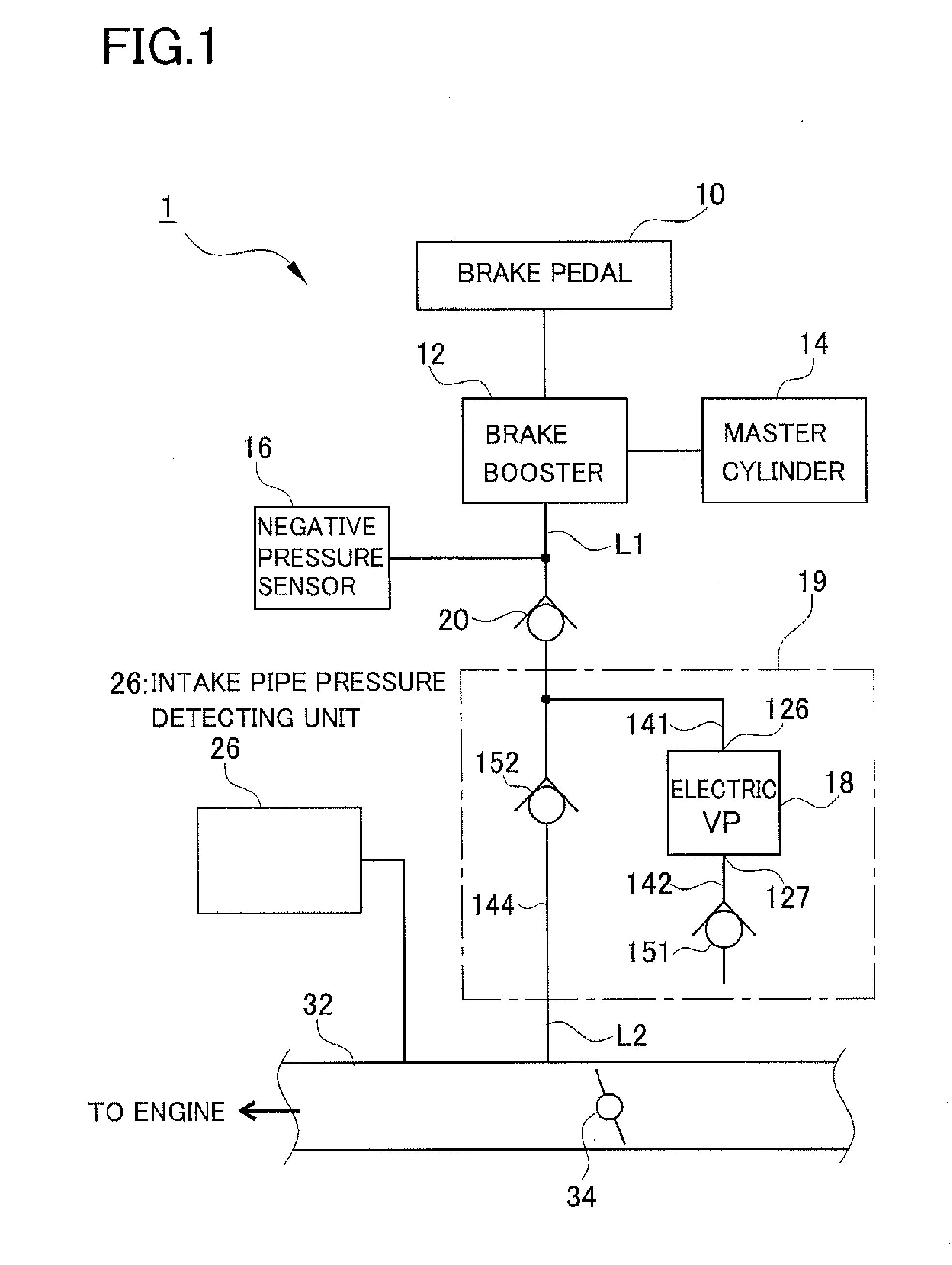
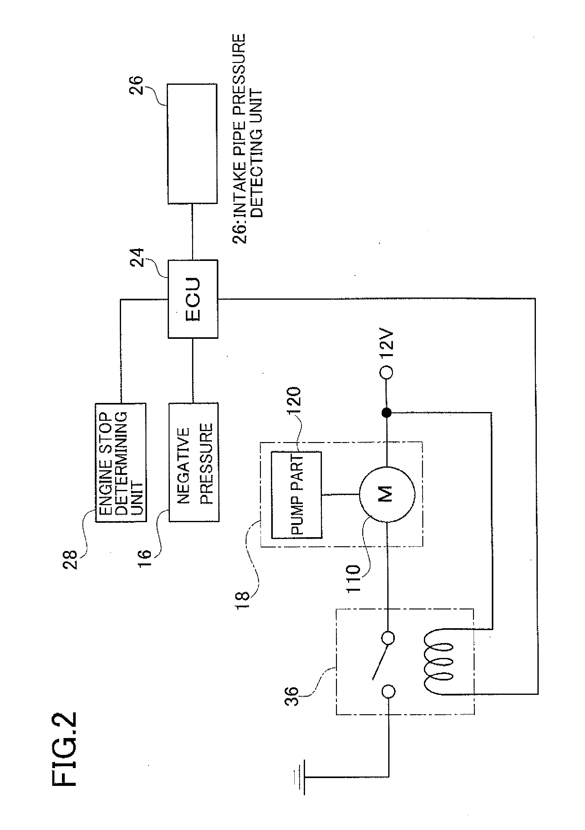
[0028]A brake system in a first embodiment will be first explained below referring to FIGS. 1 and 2. FIG. 1 is a schematic configuration view of a brake system including a negative pressure supply unit in the first embodiment. FIG. 2 is a block diagram showing a control system of the brake system including the negative pressure supply unit in the first embodiment.

[0029]A brake system 1 in the first embodiment includes, as shown in FIGS. 1 and 2, a brake pedal 10, a brake booster 12, a master cylinder 14, a negative pressure sensor 16, a negative pressure supply unit 19 including an electric vacuum pump 18 (labeled “Electric VP” in the figure), a check valve 20, an ECU 24, an intake pipe pressure detection unit 26, and an engine stop determination unit 28.

[0030]The brake booster 12 is provided between the brake pedal 10 and the master cylinder 14 as shown in FIG. 1. This brake booster 12 generates an assist force at a predetermined boosting ratio to a tread force on ...

Example

Second Embodiment

[0056]A second embodiment will be explained below. The second embodiment is basically identical in configuration to the first embodiment excepting that a discharge passage is connected to a branch passage without being open to the atmosphere as shown in FIG. 6. Thus, the following explanation is made with a focus on different configurations from the first embodiment, and explanations of similar or identical configurations are arbitrarily omitted. FIG. 6 is a schematic configuration view of a brake system including a negative pressure supply unit in the second embodiment.

[0057]Therefore, the negative pressure supply unit in the second embodiment will be explained below referring to FIGS. 6 and 7. FIG. 7 is a cross sectional view of the negative pressure supply unit in the second embodiment. In a negative pressure supply unit 19a in the second embodiment, an outlet of the discharge passage 142 is connected to the branch passage 144 as shown in FIG. 7. To be more spec...

Example

Third Embodiment

[0060]A third embodiment will be explained lastly. The third embodiment is basically identical in configuration to the second embodiment excepting that the discharge passage is switched between connecting to the branch passage and opening to the atmosphere as shown in FIG. 12. The following explanation is therefore given with a focus on different configurations from the second embodiment, and explanations of similar or identical configurations are arbitrarily omitted. FIG. 12 is a schematic configuration view of a brake system including a negative pressure supply unit in the third embodiment.

[0061]The negative pressure supply unit in the third embodiment will be explained below referring to FIGS. 12 and 13. FIG. 13 is a cross sectional view of the negative pressure supply unit in the third embodiment. In a negative pressure supply unit 19b in the third embodiment, the discharge passage 142 is connected to the branch passage 144 and also is open to the atmosphere as ...


PUM


Abstract

A negative pressure supply unit includes an electric vacuum pump including a motor part and a pump part placed in a case, and a cover member closing the case and is configured to supply negative pressure generated by the pump or in an engine intake pipe to a negative pressure chamber of a brake booster. The cover member includes: a suction passage for sucking a fluid from the negative pressure chamber into the pump part; a discharge passage for discharging the fluid ejected from the pump part to pump outside; and a branch passage branching from the suction passage to connect to an engine intake system. A first check valve provided in the discharge passage permits a fluid to flow only in a discharge direction. A second check valve provided in the branch passage permits a fluid to flow from the suction passage to the intake system.

Description

CROSS-REFERENCE TO RELATED APPLICATIONS[0001]This application is based upon and claims the benefit of priority from the prior Japanese Patent Application No. 2012-236341 filed on Oct. 26, 2012, the entire contents of which are incorporated herein by reference.BACKGROUND OF THE INVENTION[0002]1. Field of the Invention[0003]The present invention relates to a negative pressure supply unit for supplying negative pressure to a negative pressure chamber of a brake booster of a vehicle such as a motorcar.[0004]2. Related Art[0005]A brake device for vehicle is provided with a brake booster for amplifying a braking force by utilizing negative pressure in an intake pipe (“intake-pipe negative pressure”) of an engine. In recent years, pumping loss is reduced in response to demands for low-fuel consumption and thus the negative pressure in the intake pipe tends to decrease. Furthermore, for a hybrid vehicle, an electric vehicle, or a vehicle with an idling stop function, there is a case where t...

Claims


Application Information

Patent Timeline
IPC IPC(8): B60T13/18
CPCB60T13/18B60T17/02F04C25/02F04C29/126F04C18/344
Inventor SUGIMOTO, ATSUSHIMAKINO, KATSUHIKOYAMANAKA, SHOTA
Owner AISAN IND CO LTD
Why Eureka
Try Eureka