Particulate trap regeneration system and method

Inactive Publication Date: 2007-08-30
EATON CORP
View PDF13 Cites 8 Cited by
  • Summary
  • Abstract
  • Description
  • Claims
  • Application Information

AI Technical Summary

Benefits of technology

[0005] The present invention is directed to a particulate trap regeneration system having a simplified configuration. The system includes an exhaust pipe that is connected between an engine and a particulate trap and an air pump that is connected to the exhaust pipe near the engine. A fuel injector and a burner supply fuel and heat to the trap so that the particulates in the trap can be burned off.
[0006] The exhaust pipe includes two channels, one of which carries exhaust from the engine and the other of which carries air from the pump. The two channels have one common wall so that heat from the exhaust is absorbed by the air from the air pump. Because the a

Problems solved by technology

However, over time, the trap becomes too full to filter exhaust effectively and requires regeneration before it can accumulate more particulate matter.
These systems, however, tend to require complicated routing to accommo

Method used


Image

  • Particulate trap regeneration system and method
  • Particulate trap regeneration system and method
  • Particulate trap regeneration system and method

Examples


Example

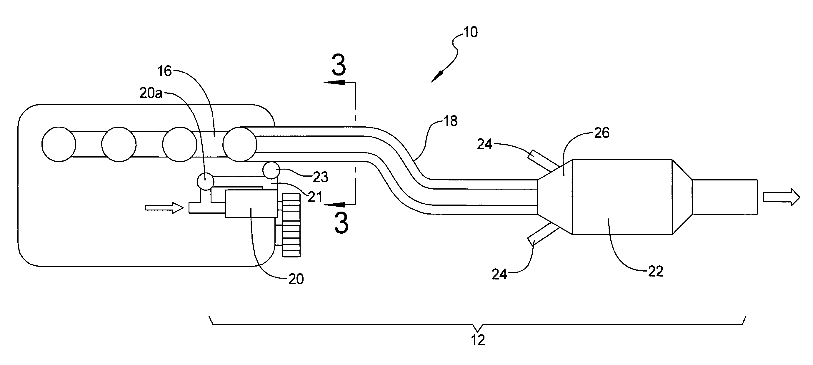
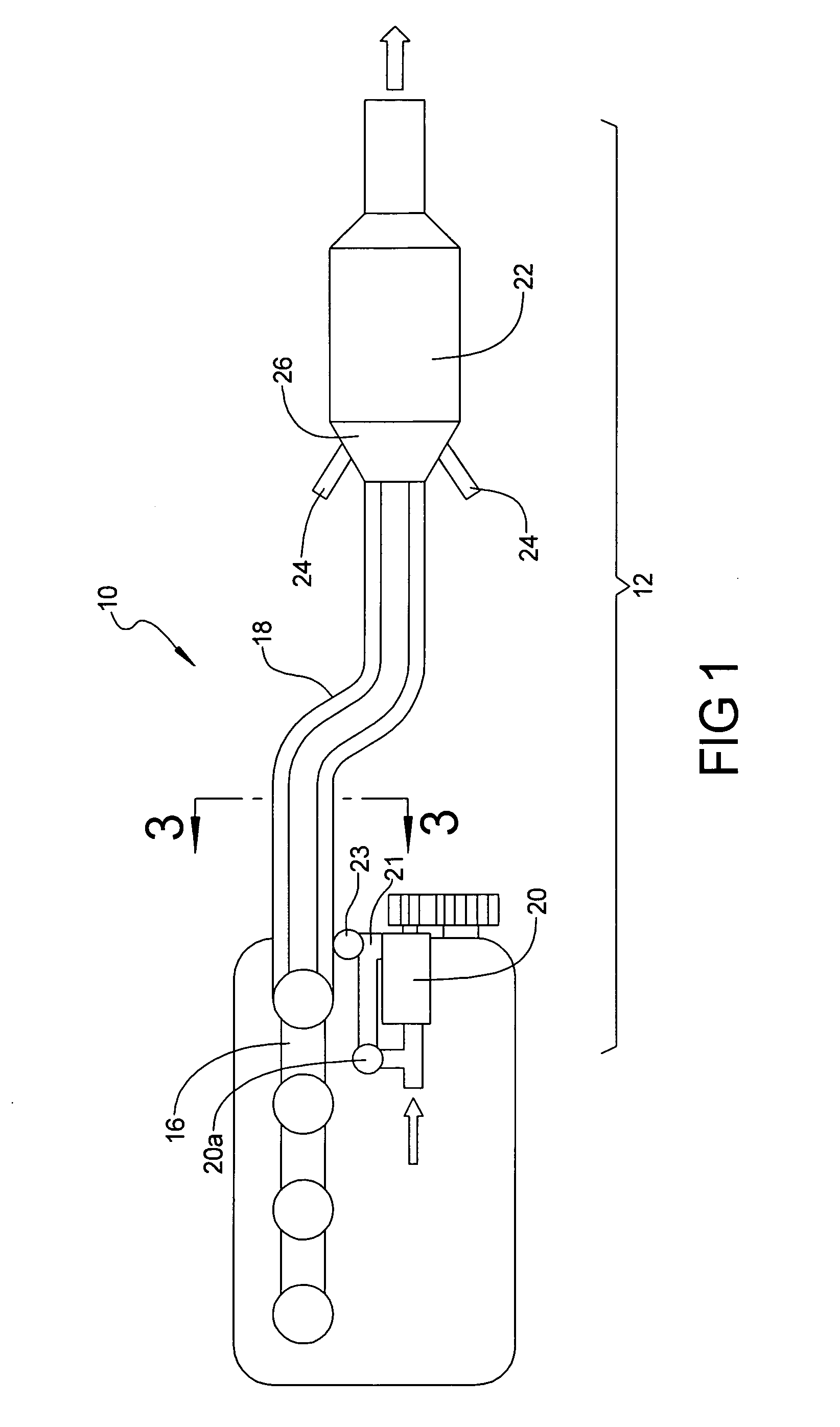
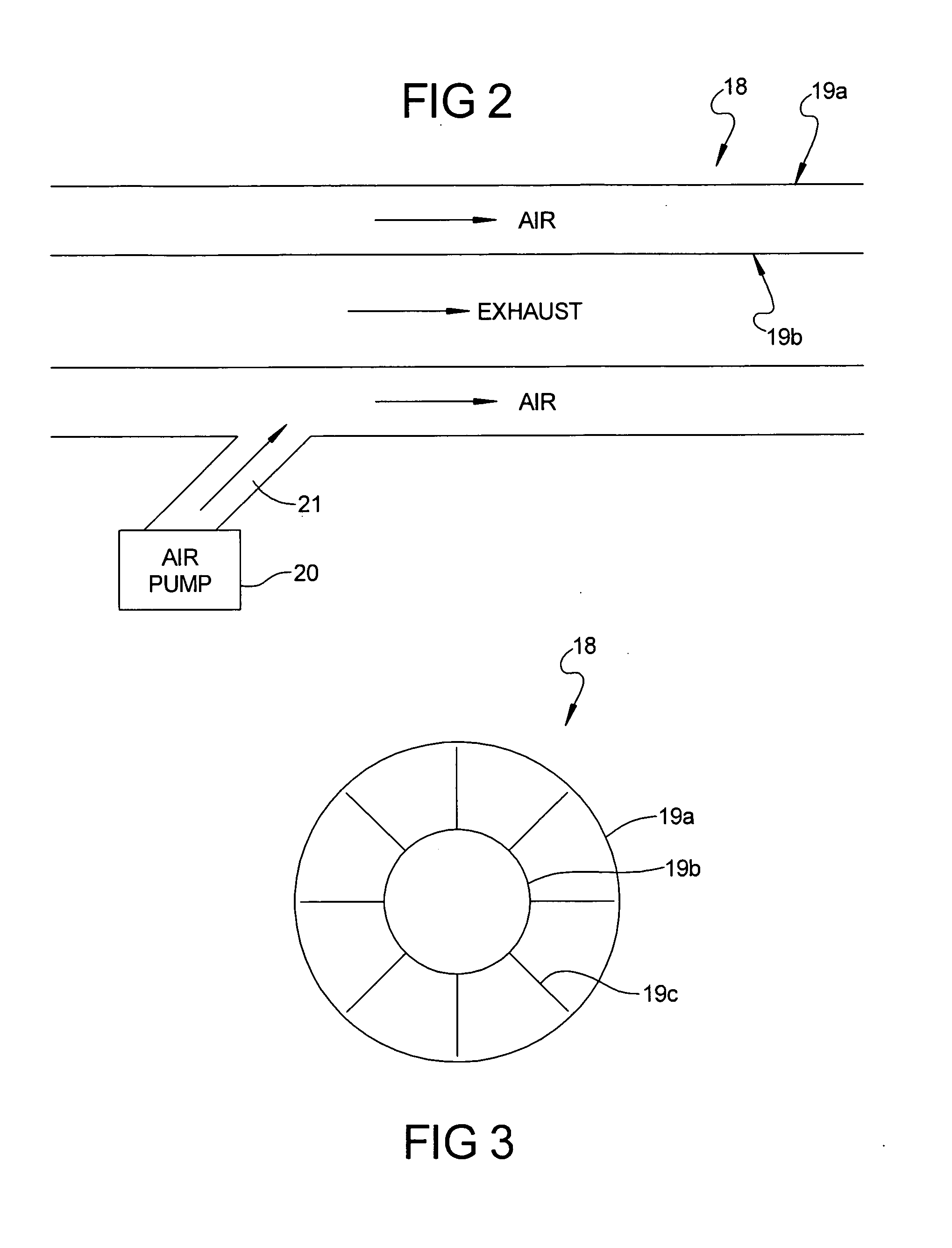
[0011]FIG. 1 shows an engine system 10 that incorporates a particulate trap regeneration system 12 according to one embodiment of the invention. The engine system 10 includes an engine 14 having an exhaust manifold 16 that sends exhaust through an exhaust pipe 18. In one embodiment, the exhaust pipe 18 has a double-walled 19a, 19b structure that keeps the outside of the exhaust pipe 18 relatively cool (FIG. 2). The double walled exhaust pipe 18 also provides a space 19c between the walls for air to flow through and be heated by heat radiating through the inner wall 19b from the exhaust. Note that other exhaust pipe configurations are possible without departing from the scope of the invention as long as there are two pipe channels that share at least one wall through which heat from the exhaust in one channel is captured by air traveling through the adjoining channel.

[0012] To further promote heat transfer, the exhaust pipe 18 may include a plurality of fins 19c that extend radially...


PUM


Abstract

A particulate trap regeneration system has an exhaust pipe that is connected between an engine and a particulate trap and an air pump that is connected to the exhaust pipe near the engine. The exhaust pipe has a double-walled configuration where the exhaust travels within the pipe and air from the air pump travels within the space between the walls, capturing heat from the exhaust. This configuration also keeps the outside of the exhaust pipe cool, improving safety and durability. Because the air entering the trap is near the exhaust temperature, the burner requires less energy to raise the temperature of the particulates sufficiently to promote burning.

Description

TECHNICAL FIELD [0001] The present invention relates to management of particulates in diesel engine exhaust, and more particularly to a particulate trap regeneration system. BACKGROUND OF THE INVENTION [0002] As is known in the art, burning diesel fuel generates particulates that need to be filtered and contained. Diesel engine systems normally incorporate a particulate trap having a filter that captures particulates from the exhaust. However, over time, the trap becomes too full to filter exhaust effectively and requires regeneration before it can accumulate more particulate matter. Regeneration is usually conducted by burning the particulates within the trap, which requires an external burner to increase the temperature of the particulates. [0003] Currently known systems provide a separate exhaust path and a diverter valve for temporarily diverting exhaust away from the trap during regeneration. Burning is enhanced by adding fuel, oxygen, and / or a catalyst to the particulates beca...

Claims


Application Information

Patent Timeline
IPC IPC(8): F01N3/00F01N3/10F01N13/08
CPCF01N3/025F01N3/0253F01N3/029F01N3/30F01N3/306Y02T10/47F01N9/002F01N13/143F01N2240/14F01N2470/24F01N3/32Y02T10/40
Inventor EYBERGEN, WILLIAM N.SHAMIS, DMITRY A.
Owner EATON CORP
Why Eureka
Try Eureka