Luminaire and illumination system

a technology of illumination system and luminaire, which is applied in the field of luminaire, can solve the problems of limited dimensions, excessive contrast between bright and dark areas, and the luminaire still has the drawback of not fully meeting the glare restrictions, and achieves the effect of great freedom of form

Active Publication Date: 2011-07-07
KONINKLIJKE PHILIPS ELECTRONICS NV
View PDF3 Cites 53 Cited by
  • Summary
  • Abstract
  • Description
  • Claims
  • Application Information

AI Technical Summary

Benefits of technology

[0035]The invention also relates to an illumination system comprising at least one luminaire according to the invention. The illumination system is understood to be combinations of at least two luminaires for general lighting purposes, for example, office lighting or, alternatively, backlighting systems, for example, TV sets and monitors, displays, for example, liquid crystal displays used in portable computers and / or (portable) telephones. The illumination system preferably comprises two luminaires with coinciding planes P, said two luminaires facing each other and bordering each other with the first end of their diffusely reflective part. Such a configuration has the advantage that it can be treated as a single luminaire.
[0036]The invention allows realization of low-height, high-comfort luminaires with great freedom of form. The invention may relate to a single luminaire. Alternatively, the invention may relate to the base component for realization of a variety of indoor and outdoor illumination systems, which can be achieved by including extra beaming optics, such as louvers or collimating panels, at the light exit window of the optical system. The invention is suitable for realization of high-quality displays or for backlighting imaging and non-imaging devices.

Problems solved by technology

However, by replacing a fluorescent lamp with one or more LEDs, the limited dimensions of this light source offer an extra design challenge because its concentrated brightness must be distributed on a larger surface in order to create an acceptable luminance which is not disturbing to the user.
Though said luminaire is an improvement in comparison with the known prior art, the described luminaire still has the drawback that it does not fully comply with the glare restrictions set by the EN12464 norm.
Glare results from excessive contrast between bright and dark areas in the field of view.
Another drawback is that light is still emitted through the light exit window directly by the specularly reflective part of the reflective screen, i.e. not via its diffusely reflective part, so that light source images still remain visible in the specularly reflective part and increase the risk of glare.

Method used


Image

  • Luminaire and illumination system
  • Luminaire and illumination system
  • Luminaire and illumination system

Examples


Embodiment Construction

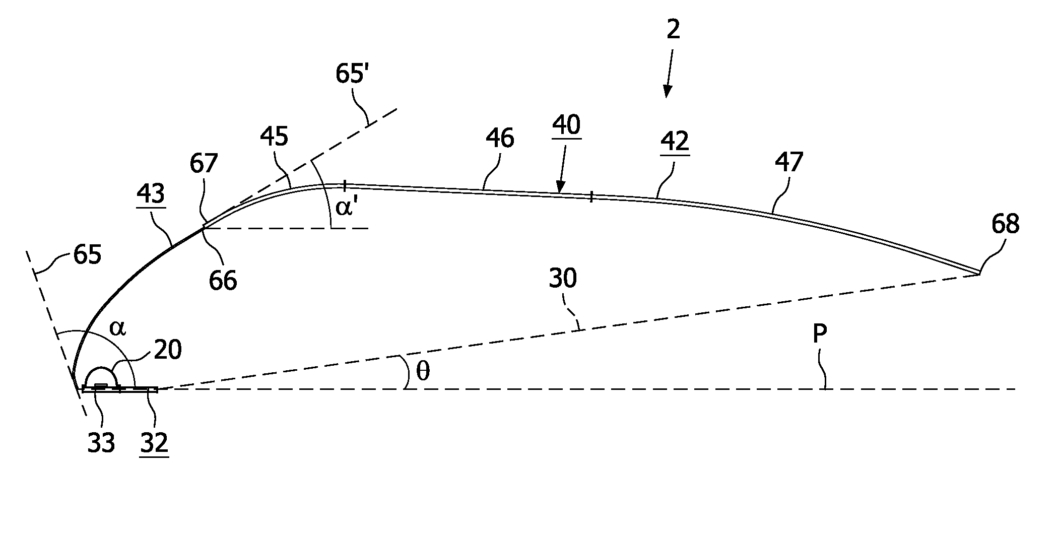
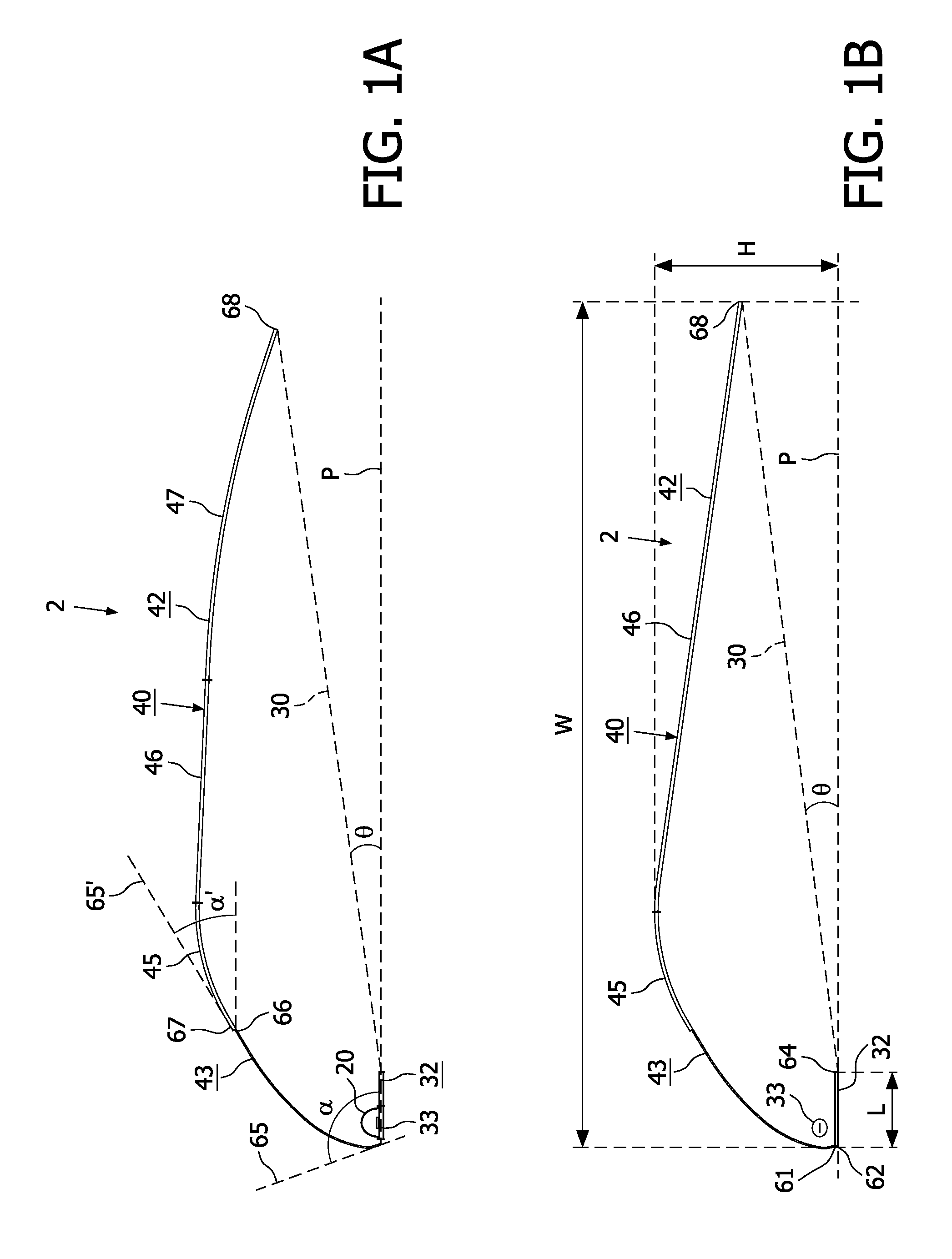
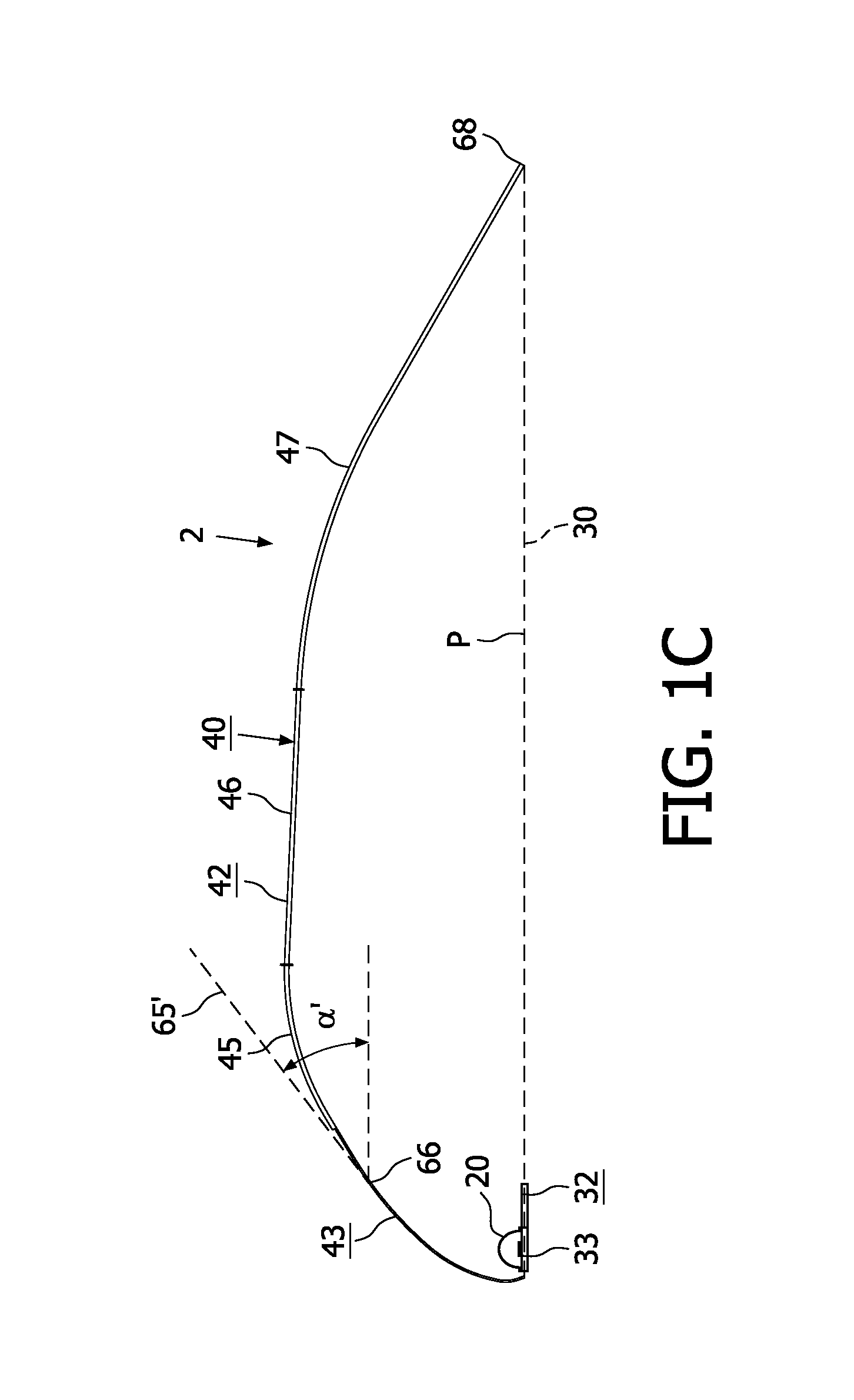
[0047]FIGS. 1A, 1B and 1C are cross-sectional views of a luminaire 2 according to the invention. The luminaire 2 comprises a light exit window 30 for emitting light from the luminaire 2 and a reflective screen 40 arranged opposite the light exit window 30. The luminaire 2 further comprises a light source 20 which is arranged for indirect illumination of the light exit window 30 via a diffusely reflective part 42 of the reflective screen 40 which further comprises a specularly reflective part 43. The light source 20 is held in electric contacting means 33 and arranged near the light exit window 30. Shielding means 32 define an imaginary plane P substantially parallel to the light exit window 30 and shield the contacting means 33 from being directly viewed by an observer through the light exit window 30. The specularly reflective part 43 is concavely shaped towards the light exit window 30 for reflecting at least part of the light emitted by the light source 20 towards the diffusely r...


PUM

PropertyMeasurementUnit
angleaaaaaaaaaa
angle αaaaaaaaaaa
angleaaaaaaaaaa

Abstract

The invention relates to a luminaire (2) and an illumination system (12). The luminaire according to the invention comprises a light exit window (30) for emitting light from the luminaire, and a reflective screen (40) arranged opposite the light exit window. The luminaire further comprises a light source (20) which is arranged for indirect illumination of the light exit window via the reflective screen. The light source is arranged near the light exit window on an imaginary plane P substantially parallel to the light exit window and emits light away from the light exit window. The luminaire further comprises a specularly reflective part (43) as part of the reflective screen, which specularly reflective part is concavely shaped for reflecting at least part of the light emitted by the light source towards a diffusely reflective part (42) of the reflective screen.
The luminaire according to the invention has the effect that use of the specularly reflective part allows an improved controlled reflection of the portion of the light emitted by the light source towards the diffusely reflective part.

Description

FIELD OF THE INVENTION[0001]The invention relates to a luminaire for indirect illumination, having a light exit window for emitting light from the luminaire.[0002]The invention also relates to an illumination system comprising the luminaire according to the invention.BACKGROUND OF THE INVENTION[0003]Traditional luminaires based on fluorescent lamps are more and more replaced by LED-based luminaires. Indeed, LEDs provide great freedom of design and energy advantages. However, by replacing a fluorescent lamp with one or more LEDs, the limited dimensions of this light source offer an extra design challenge because its concentrated brightness must be distributed on a larger surface in order to create an acceptable luminance which is not disturbing to the user.[0004]Luminaires of the type described in the opening paragraph are known per se. They are used, inter alia, as luminaires for general lighting purposes, for example, for office or shop lighting, for example, shop window lighting o...

Claims


Application Information

Patent Timeline
Patent Type & Authority Applications(United States)
IPC IPC(8): F21V9/16F21V7/00F21V9/00F21V9/40F21Y101/00
CPCF21S8/00F21V7/0008F21V7/0016F21V7/09F21S4/20F21Y2103/10F21Y2103/33F21Y2113/13F21Y2115/10F21V7/30F21V9/40F21V7/04
Inventor HOLTEN, PETRUS ADRIANUS JOSEPHUSTORDINI, GIORGIAFABRIEK, VINCENT
Owner KONINKLIJKE PHILIPS ELECTRONICS NV
Why Eureka
Try Eureka