Control apparatus for multi-phase rotary machine

a control apparatus and multi-phase technology, applied in the direction of motor/generator/converter stopper, dynamo-electric gear control, dynamo-electric converter control, etc., can solve the problem of increasing the hardware size of the inverter, and reducing the service life of the inverter

Inactive Publication Date: 2011-07-14
DENSO CORP
View PDF2 Cites 24 Cited by
  • Summary
  • Abstract
  • Description
  • Claims
  • Application Information

AI Technical Summary

Benefits of technology

[0017]It has been found that such a form of control enables the frequency of switching operations (frequency of changes in switched status of the switching elements) ...

Problems solved by technology

The switching frequency of the inverter can thereby be limited.
However with such prior art methods, although the switching frequency of the inverter can be limited, it is not possible to avoid a c...

Method used


Image

  • Control apparatus for multi-phase rotary machine
  • Control apparatus for multi-phase rotary machine
  • Control apparatus for multi-phase rotary machine

Examples


second embodiment

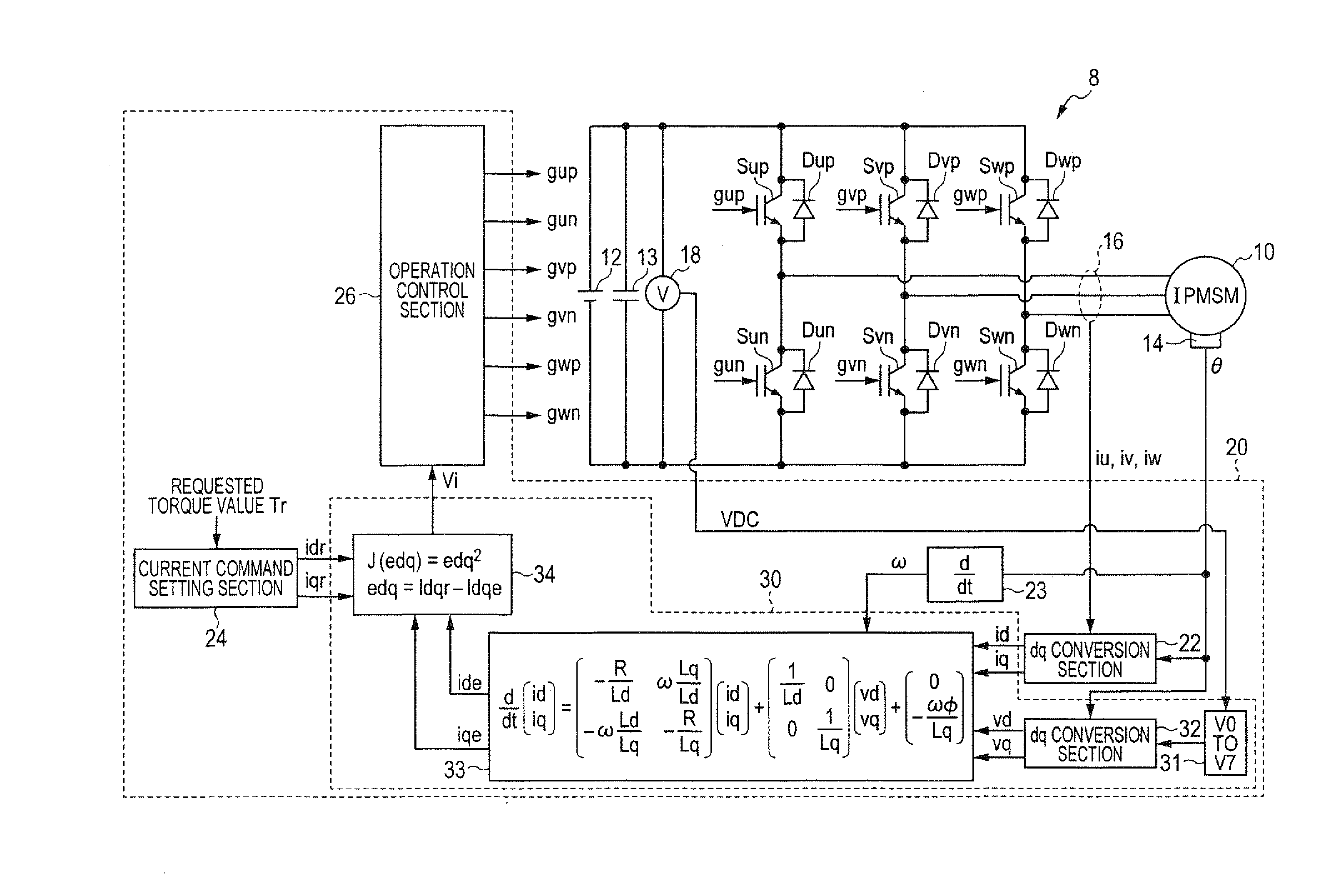
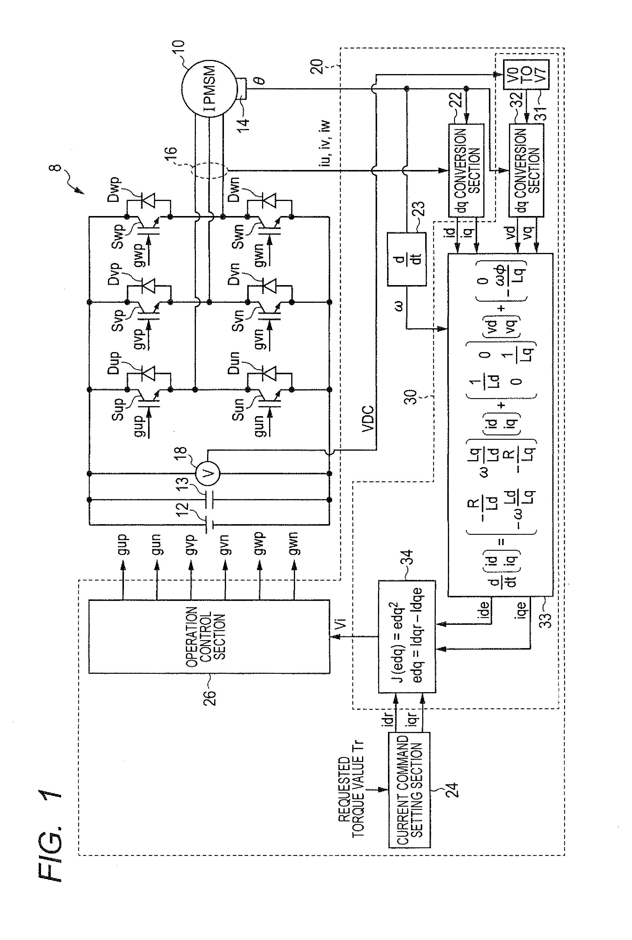
[0075]A second embodiment of a control apparatus for an inverter of a IPMSM will be described in the following referring to FIG. 8. Only points of difference between this embodiment and the first embodiment of FIG. 1 will be described in detail, and components of the second embodiment which correspond to components of the first embodiment are designated by identical reference numerals to those of FIG. 1.

[0076]The second embodiment essentially differs from the first embodiment in that the direct control quantities (quantities whose values are predicted for use in evaluation processing for determining the next operation state of the inverter) are torque and magnet flux. The predicted current vector values ide(n+2), iqe(n+2) for the control period (n+1) following the control period (n) are derived as described above for the first embodiment. However with the second embodiment, this predicted current vector is then converted by a torque / magnetic flux determining section 37 to a correspo...


PUM


Abstract

A control apparatus controls an inverter (electric power converter circuit) which is connected for selectively applying a plurality of voltage levels to each phase of a polyphase rotary machine. In each of successive control periods, the apparatus determines the inverter operation state (combination of respective voltage levels applied to the phases) to be set for the succeeding control period, by performing prediction calculations based on a model of the rotary machine, for each of a plurality of candidates for the next operation state, to select an optimum candidate. The candidates are restricted to those operation states whereby the voltage level of no more than one of the phases will be changed, at changeover to the operation state of the next control period.

Description

CROSS-REFERENCE TO RELATED APPLICATIONS[0001]This application is based on and incorporates herein by reference Japanese Patent Application No. 2010-3490 filed on Jan. 11, 2010.BACKGROUND OF THE INVENTION[0002]1. Field of Application[0003]The present invention relates to a control apparatus for controlling a control quantity of a polyphase rotary machine, by controlling an inverter (electric power converter circuit) having switching elements connected to the phases of the rotary machine, the switching elements being operated to selectively connect each of the phases to at least two different DC voltage levels.[0004]2. Description of Related Art[0005]It is known, for example as described in Japanese patent application publication No. 2006-174697 (designated in the following as reference 1), that such a type of control apparatus can utilize predictive control by applying a mathematical model, for maintaining the torque or stator magnet flux values of a rotary machine within a predeterm...

Claims


Application Information

Patent Timeline
IPC IPC(8): H02P6/14H02P21/05H02P21/00H02P21/14H02P21/18H02P21/22H02P21/24H02P23/04H02P23/07H02P23/14H02P27/04H02P27/08H02P29/00
CPCH02P21/0035H02P2207/05H02P23/14H02P21/148H02P21/22H02P21/20
Inventor TAKAHASHI, TOMOYAIMURA, AKIHIRO
Owner DENSO CORP
Why Eureka
Try Eureka