Ring binder mechanism having dual time buffer actuator

a time buffer actuator and ring binder technology, applied in the field of ring binder mechanism, can solve the problems of user injury, inability to retain loose-leaf pages, and risk of rings inadvertently opening

Active Publication Date: 2011-07-14
WORLD WIDE STATIONARY MFG CO LTD
View PDF99 Cites 34 Cited by
  • Summary
  • Abstract
  • Description
  • Claims
  • Application Information

AI Technical Summary

Problems solved by technology

If this spring force is strong, there is a risk that a user could be injured by getting a finger pinched between the ring members as the housing causes them to snap shut during closing.
However, the absence of a ...

Method used


Image

  • Ring binder mechanism having dual time buffer actuator
  • Ring binder mechanism having dual time buffer actuator
  • Ring binder mechanism having dual time buffer actuator

Examples


first embodiment

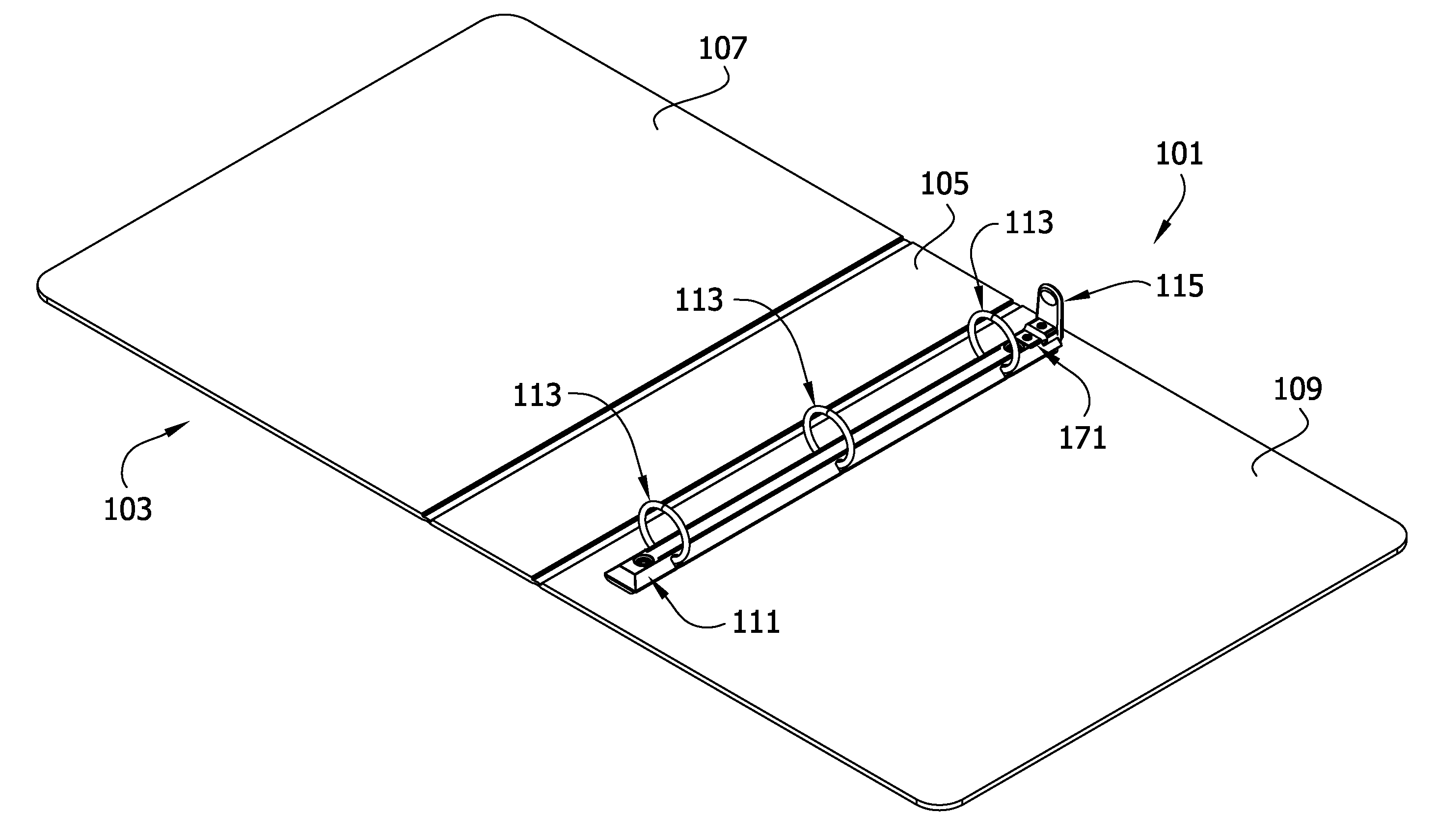
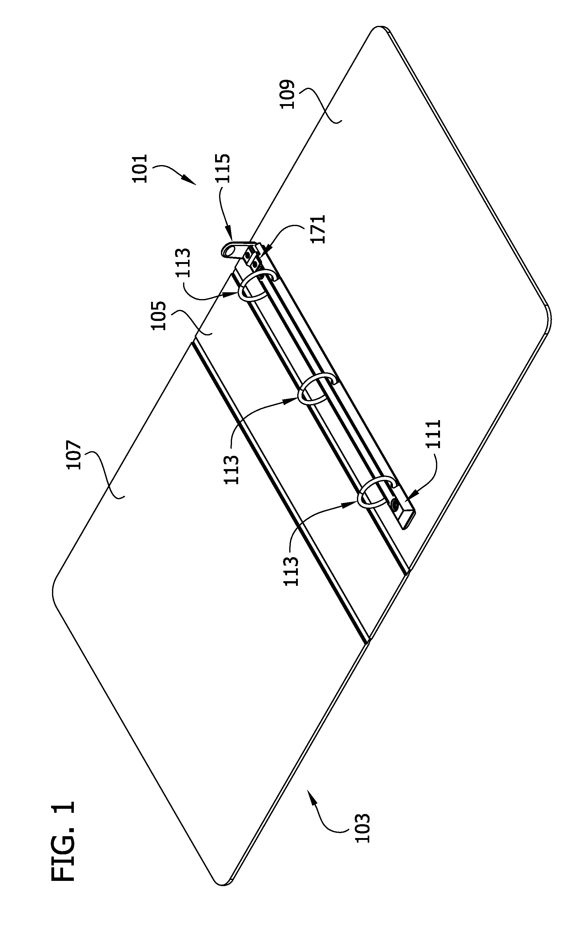
[0026]Referring to the drawings, FIGS. 1-2 show a ring binder mechanism of the invention, generally indicated at 101. In FIG. 1, the mechanism 101 is mounted on a notebook cover 103. Specifically, the mechanism 101 is mounted adjacent the spine 105 of the notebook cover 103. The spine 105 extends between front and back covers 107, 109 that are hingedly attached to the spine 105. The front and back covers 107, 109 are moveable to selectively cover or expose loose-leaf pages (not shown) retained by the mechanism 101. Ring binder mechanisms mounted on a notebook cover in other ways (e.g., on the spine) or on substrates other than a notebook cover (e.g., a file, a briefcase, etc.) do not depart from the scope of this invention.

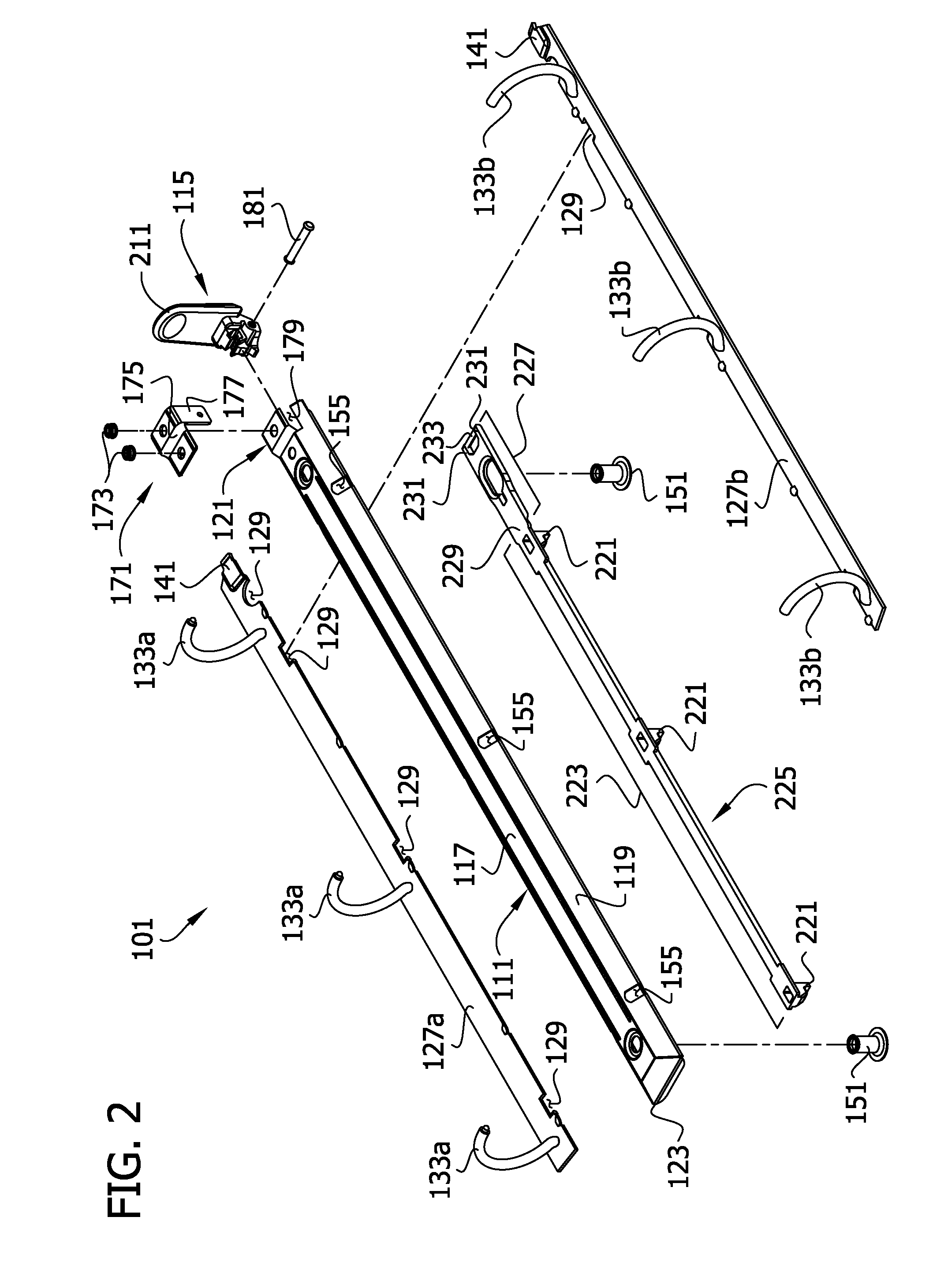
[0027]As shown in FIGS. 1 and 2, the mechanism 101 includes an elongate housing 111 supporting a plurality of rings (each of which is designated generally 113). The housing 111 has a generally rectangular perimeter. The housing 111 also has a raised flat central p...

second embodiment

[0063]FIGS. 8 and 9 illustrate a ring mechanism, generally designated 301. Except as noted, the ring mechanism 301 is substantially the same as the ring mechanism 101 described above and illustrated in FIGS. 1-7C. The travel bar 325 in this ring mechanism 301 does not include a connector portion formed integrally with the locking portion 323. Instead, the locking portion 323 of the travel bar 325 is connected to the actuator 115 by a separate connector 327. As illustrated, in FIGS. 8 and 9, the connector 327 is a wire link. Opposing ends 333 of the wire link 327 are received in the recess 255 in the actuator 115 and perform in a manner analogous to the cross bar 233 of the ring mechanism 101 described above. Use of a separate wire link connector to connect the locking portion of a travel bar to an actuator is disclosed in greater detail in commonly-owned application Ser. No. 11 / 610,358 (Published as US 20080124166), which is hereby incorporated by reference, and need not be discusse...

third embodiment

[0064]a ring mechanism, generally designated 401, is illustrated in FIGS. 10-14E. This embodiment is substantially identical to the ring mechanism 101 described above, except as noted. The closing arm 403 of the actuator 415 in this embodiment, includes a rib 420 connecting the closing arm to the actuator handle 411. The rib 420 enhances the stiffness of the closing arm 403. The rib 420 also splits the flexible arm into two separate flexible arms 451 extending generally from the actuator body 421. In the illustrated embodiment, the flexible arms 451 are substantially identical. The arms 451 are spaced from the rib 420 on opposite sides thereof to facilitate movement of the arms independently of the rib 420.

[0065]As best illustrated in FIG. 14A, each flexible arm 451 in its undeformed state is attached at one end 460 to the body 421 of the actuator. The arm 451 curves upward at a first bend 462 relatively close to the attached end 460. The first bend 462 in the arm is a relatively sh...


PUM


Abstract

A ring mechanism has an elongate housing and rings for holding loose-leaf pages. Each ring has ring members mounted on pivoting hinge plates for movement between open and closed positions. An actuator has opening and closing arms extending from an actuator body for opening and closing the rings. The mechanism has a travel bar moveable between a locked position in which a locking element blocks pivoting movement of the hinge plates and an unlocked position. The actuator has a flexible arm positioned to push the travel bar toward the locked position when the actuator closes the rings. At least a portion of the flexible arm is adapted to deform during closing in a manner that includes rotation in a first direction relative to the body of the actuator. Movement of the actuator to close the rings includes rotation of the actuator in the first direction relative to the housing.

Description

FIELD OF INVENTION[0001]This invention relates to a ring binder mechanism for retaining loose-leaf pages, and in particular to an improved ring binder mechanism for opening and closing ring members and for locking closed ring members together.BACKGROUND OF THE INVENTION[0002]Ring binder mechanisms retain loose-leaf pages on rings. Ring binder mechanisms can be used in notebooks, files, briefcases, clipboards and other similar objects to give the object a loose-leaf page retaining function. A conventional ring binder mechanism has rings formed by ring members that are selectively moveable to open the rings to add and / or remove loose leaf pages and close the rings to retain loose-leaf pages on the rings. The ring members are commonly mounted on adjoining hinge plates supported by a housing for pivoting movement between open and closed positions. The undeformed housing is slightly narrower than the combined width of the hinge plates such that the housing applies a spring force that bia...

Claims


Application Information

Patent Timeline
IPC IPC(8): B42F3/04
CPCB42F13/26
Inventor HUANG, MING HUALI, YUN LONG
Owner WORLD WIDE STATIONARY MFG CO LTD
Why Eureka
Try Eureka