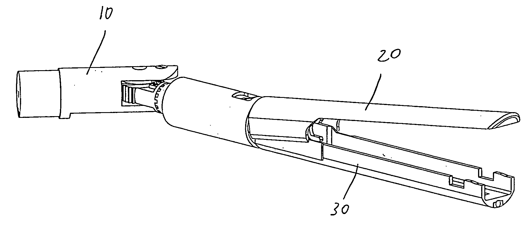
Method for operating a surgical stapling and cutting device

a cutting device and surgical stapling technology, applied in the field of surgical stapling instruments, can solve the problems of inconvenient operation of the firing bar, limited control of the u.s. surgical corp. stapler, and distracting the clinician from the effect of the operation

Inactive Publication Date: 2007-03-29
CILAG GMBH INT
View PDF43 Cites 2086 Cited by
  • Summary
  • Abstract
  • Description
  • Claims
  • Application Information

AI Technical Summary

Benefits of technology

[0022] Another advantage of the present invention is that the movable distal end effector is center-biased. This means that the distal end is, first, freed from a stable position and is, then, passively moved into its new position by pressing the end effector against a feature of the environment, such as surrounding tissue. When the actuator that frees the end effector from the stable position is released, the distal end effector returns to its center position under the urging of a center-biasing device, preferably, at least one biasing spring, in particular, two biasing springs imparting a biasing force in opposing and, therefore, centering directions. Alternatively, the center-biasing device can be a set of spring-loaded plungers disposed on either side of the end effector at the clevis to urge the end effector independently towards a center position.
[0023] The trigger that controls the passive movement is normally locked. This lock is released by pulling in the trigger. Once the distal end effector is in a desired position, the user releases the trigger, thereby locking distal end effector in the new position.
[0024] The device according to the invention is a surgical stapler and cutter or other endoscopic device that can be used, in particular, to staple sections of tissue together and cut tissue when desired. In one embodiment of the end effector, measures for carrying out both the stapling and cutting functions can be entirely contained within the distal end effector of the device.
[0025] Again, another advantage of the present invention is that the handle is electronically controlled, universal, and motorized. The handle includes a microprocessor that is programmed for multiple product configurations. For example, in the case of a stapler, the handle is programmed for a 30 mm, a 45 mm, or a 60 mm staple cartridge. The distal shaft of the stapler has a proximal end that plugs into the universal handle. The distal shaft includes an array of electrical contacts that make corresponding contact with a mating array in the handle at the connection location. The contacts are unique for each of the different distal shafts and the handle “recognizes” the shaft and runs the appropriate program for it. The handle is programmed to include logic for safety lockouts, speed of stapler delivery, distance of stroke, and the like. Such modularity allows manufacture of one handle with multiple end effectors to mate thereto.
[0026] Actuation of the device is accomplished using an electric motor. The device may also be actuated by multiple electric motors, by hydraulics or pneumatics, or by the transmission of energy through a flexible drive shaft in any way such that the actuation assembly can be contained primarily or entirely in the distal portion of the device.
[0027] The work accomplished by any of these measures can be converted into desirable motions through any single or combination of screw drive, gear drive, wedge, toggle, cam, belt, pulley, cable, bearing, or the like push rod. In particular, a screw drive is used to transmit the work of the electric motor into linear motion. In one embodiment, the motor for the screw drive resides in the handle. A flexible rotating cable is connected from the motor to a threaded shaft. Thus, when the motor turns in either direction, the rotation of the flexible cable is transmitted to the threaded drive shaft and, because the stapling actuator and cutting slide is disposed on the drive shaft, both functions are carried out by distal movement of the slide. In a second embodiment, the motor resides entirely in the end effector and has a shaft connected to the slide drive shaft, either directly or through transmission gears. In such a case, all that is needed in the handle is the on / off and drive shaft direction actuators, the former for turning the motor on and off and the latter determining which direction the motor will spin.

Problems solved by technology

The U.S. Surgical Corp. stapler, however, is limited by the predetermined angles that it can achieve and by the limited side to side pivoting (−45 degrees to +45 degrees) that requires two hands for operation.
One common problem with these surgical instruments is control of the firing bar through the articulation joint.
Increased friction when articulated would be inconvenient and distracting to the clinician if required to exert a varying amount of firing force.

Method used


Image

  • Method for operating a surgical stapling and cutting device
  • Method for operating a surgical stapling and cutting device
  • Method for operating a surgical stapling and cutting device

Examples


first embodiment

[0139]FIGS. 25 and 26 illustrate a second exemplary embodiment of the stapling and cutting system 200 according to the invention. This system 200 is different than the first embodiment in that the motorized stapling assembly is entirely contained in the end effector 210. Therefore, the handle 220 only needs to have two actuating devices. The first actuating device 222 is a ball joint releasing lever and the second actuating device is the stapling / cutting motor on / off button 224.

[0140] The end effector 210 is connected to the distal end of the actuation shaft 226 of the handle 220 at a ball-joint connector 228. The end effector 210 has, at its distal-most end, a ball joint 212. The ball joint 212 has two opposing cup-shaped clamps 2122, 2124. The interior surfaces of the clamps 2122, 2124 are shaped to correspond to the outer shape of the ball joint 212. The clamps 2122, 2124 translate towards or away from one another based upon an actuation of the lever 222.

[0141] The clamps 2122, ...

second embodiment

[0144]FIGS. 27 and 28 illustrate a variation of the end effector shown in FIGS. 25 and 26. In particular, the handle 220 is the same as in FIGS. 25 and 26. However, the end effector 310 is different. Specifically, the end effector 310 has a proximal ball joint 312 similar to the ball joint 212 in FIGS. 25 and 26, but also has a second, distal ball joint 314, having a shape virtually identical to the proximal ball joint 312. Therefore, when the lever 222 is pressed down to release the ball joint 312, 314, the end effector 310 can be allowed to rest within the body and the opposite end can be grasped between the clamps 2122, 2124. In such an orientation, shown in FIG. 27, the stapling / cutting can be actuated when the jaw opening is facing the user.

[0145] It is also noted that placement of an end effector 210, 310 at a surgical site sometimes requires the access to the surgical site to be rather small in comparison to the opened jaws of the end effector 210, 310. With the ability to re...

fourth embodiment

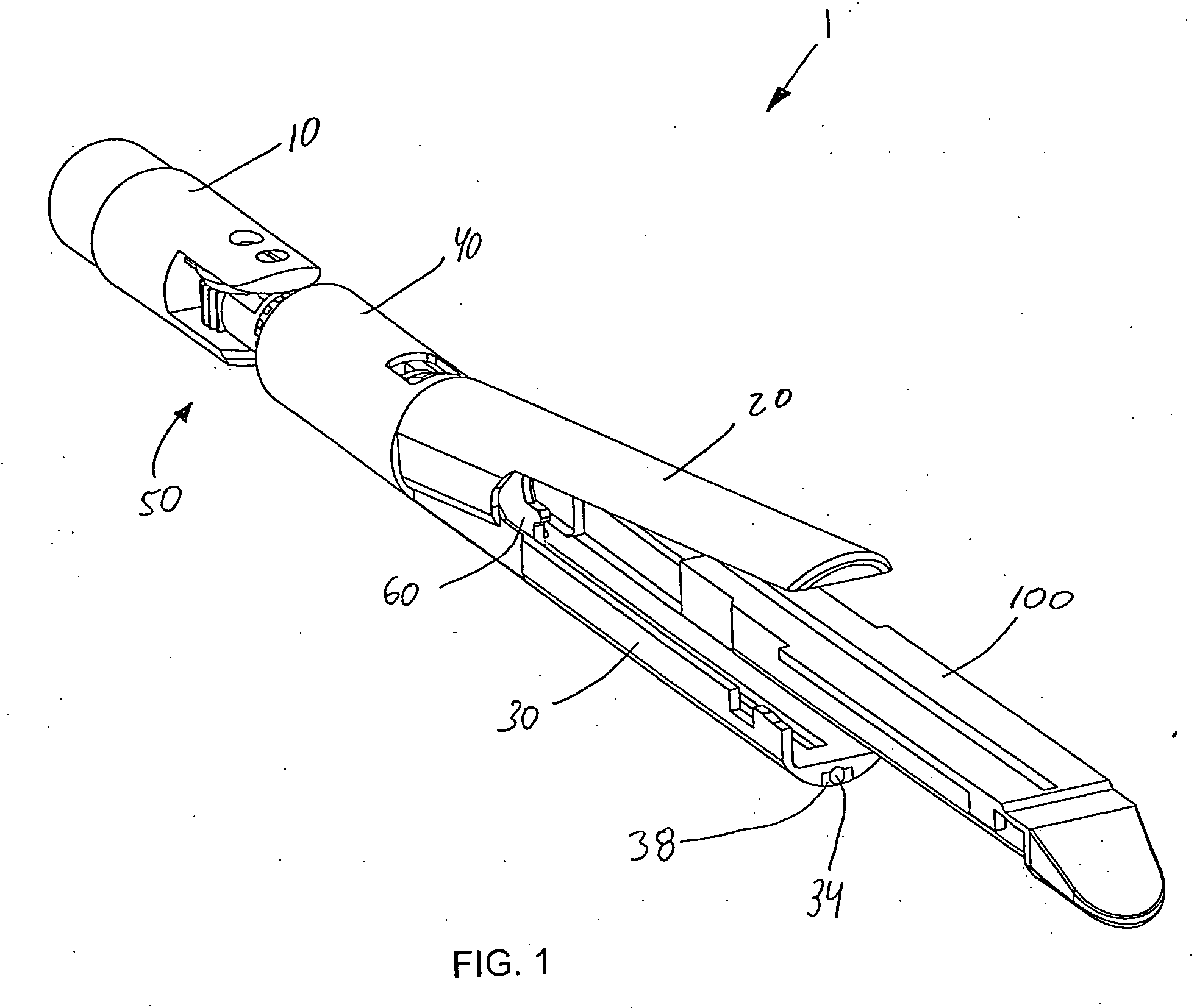
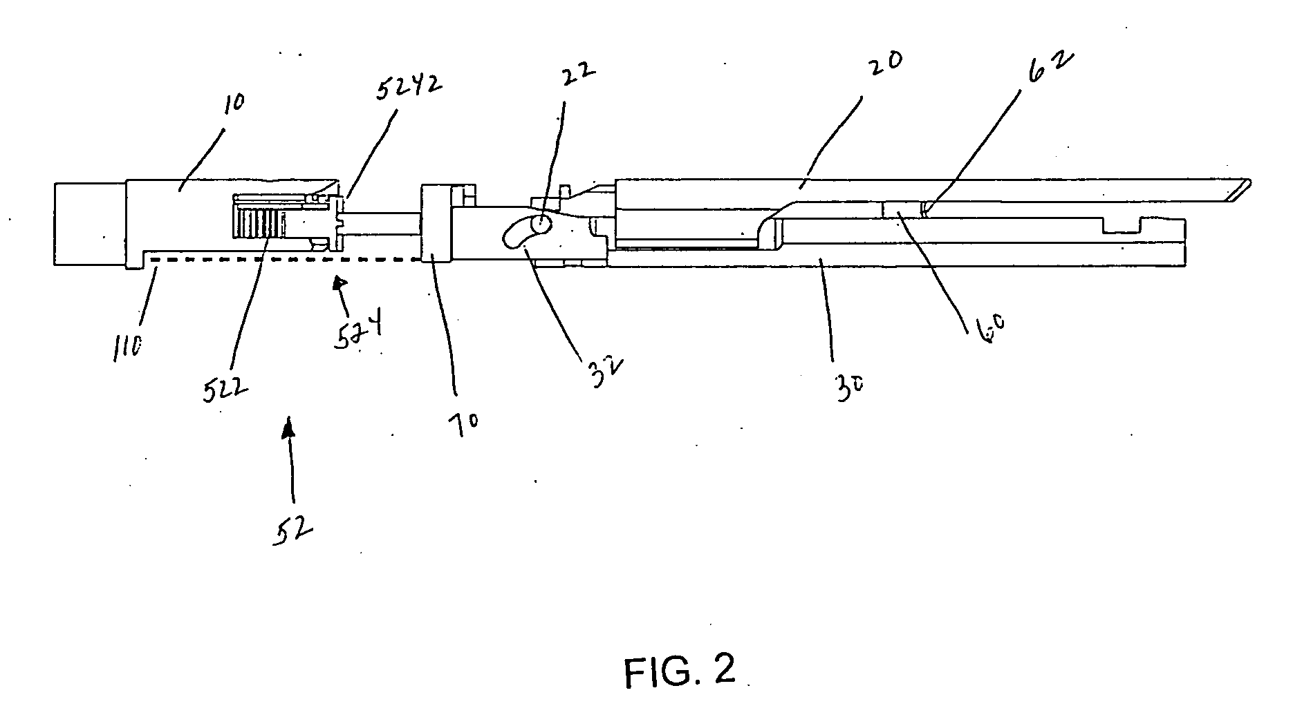
[0188]FIG. 54 shows some internal parts of this fourth embodiment of the end effector. The anvil 1020 is disposed opposite the staple cartridge holder 1030 and a closure ring 1040 surrounds the proximal end of the staple cartridge holder 1030. The inner and outer tubes 1130, 1110 are removed so that the articulation lock release slide 1120, the pushrod 1102, and the pushrod-blade support 1070 can be seen clearly. A screen door 1103 is mounted around the pushrod 1102 and inside the inner and outer tubes 1130, 1110 and the bell actuator 1100. The handle 1200 and bell actuator 1100 are removed for clarity. The screen door 1103 restricts movement of the pushrod 1102 to only one direction—distal—because the knife / cutting blade 1060 only moves in the distal direction.

[0189] The two-part clevis is best illustrated in the views of FIGS. 55 and 56. These figures show various internal features of the end effector of FIG. 54 with the outer tube 1110 removed. In the exploded view of FIG. 55, co...


PUM


Abstract

A method for operating a surgical end effector, includes articulatingly connecting a control handle to the end effector and positioning an articulation joint actuator of the handle to selectively connect with an articulation lock of the end effector such that, when unactuated, the articulation joint actuator automatically connects with the articulation lock to lock the articulation lock and temporarily prevent further articulating motion of the end effector and, when actuated, the articulation joint actuator is removed from the articulation lock to unlock the articulation lock and, thereby, permit articulating motion of the end effector dependent upon external forces acting upon the end effector. The articulation joint actuator is actuated to unlock the articulation lock and the end effector is contacted with the environment to passively articulate the end effector into a desired articulated position. Removal of actuation locks the articulation lock and retains the end effector in the desired articulated position.

Description

CROSS-REFERENCE TO RELATED APPLICATION [0001] This application claims the priority, under 35 U.S.C. § 119, of U.S. Provisional Patent Application Nos. 60 / 760,000 and 60 / 811,950, filed Jan. 18, 2006, and Jun. 8, 2006, respectively, and is a divisional of U.S. patent application Ser. No. 11 / 491,626, filed Jul. 24, 2006, which parent application claims the priority of U.S. Provisional Patent Application No. 60 / 702,643 filed Jul. 26, 2005, and application Nos. 60 / 760,000 and 60 / 811,950, the entire disclosures of which are hereby incorporated herein by reference in their entireties.STATEMENT REGARDING FEDERALLY SPONSORED RESEARCH OR DEVELOPMENT [0002] n / a FIELD OF THE INVENTION [0003] The present invention lies in the field of medical devices, in particular, in the field of surgical stapling instruments that are capable of applying lines of staples to tissue while cutting the tissue between those staple lines and, more particularly, to improvements relating to stapler instruments and imp...

Claims


Application Information

Patent Timeline
Patent Type & Authority Applications(United States)
IPC IPC(8): A61B17/08
CPCA61B2017/2931A61B2017/07271A61B2017/320052A61B17/068A61B17/07207A61B2017/2927A61B2017/00389A61B17/115A61B17/072A61B2017/07214A61B17/00234A61B2017/003A61B2017/07285
Inventor SMITH, KEVIN W.PALMER, MATTHEW A.KLINE, KOREY ROBERTDEVILLE, DEREK DEE
Owner CILAG GMBH INT
Why Eureka
Try Eureka