Corn head stripper plate adjusting mechanism

a technology of adjusting mechanism and stripper plate, which is applied in the field of corn harvesting header assembly, can solve the problems of reducing service life, reducing part cost, and increasing part cos

Active Publication Date: 2011-07-21
BLUE LEAF I P INC
View PDF28 Cites 50 Cited by
  • Summary
  • Abstract
  • Description
  • Claims
  • Application Information

AI Technical Summary

Problems solved by technology

Coupling arrangements in use today vary, but typically, a tradeoff is made between part cost and durability.
Durable or rugged designs normally result in increased part costs, but also provide increased service life.
Whether insufficiently rugged or too expensive, actuation lever adjusting mechanism and coupling arrangements in use today do not completely satisfy the customer—the farm operator.

Method used


Image

  • Corn head stripper plate adjusting mechanism
  • Corn head stripper plate adjusting mechanism
  • Corn head stripper plate adjusting mechanism

Examples


Embodiment Construction

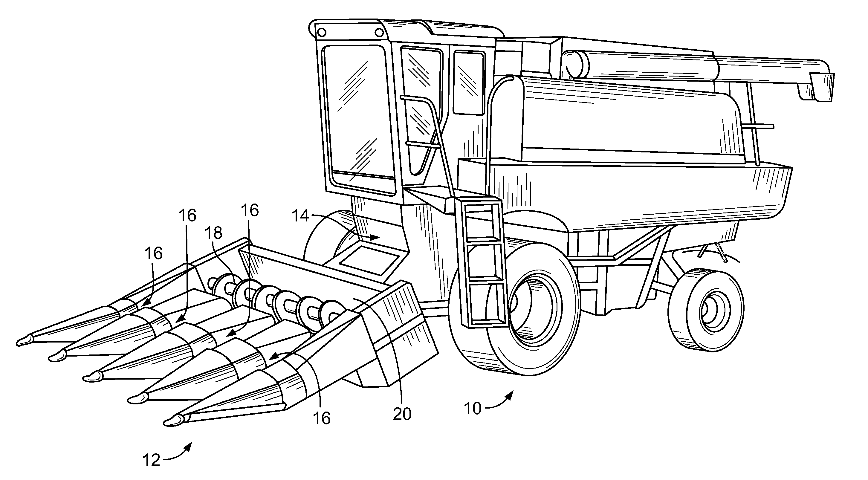
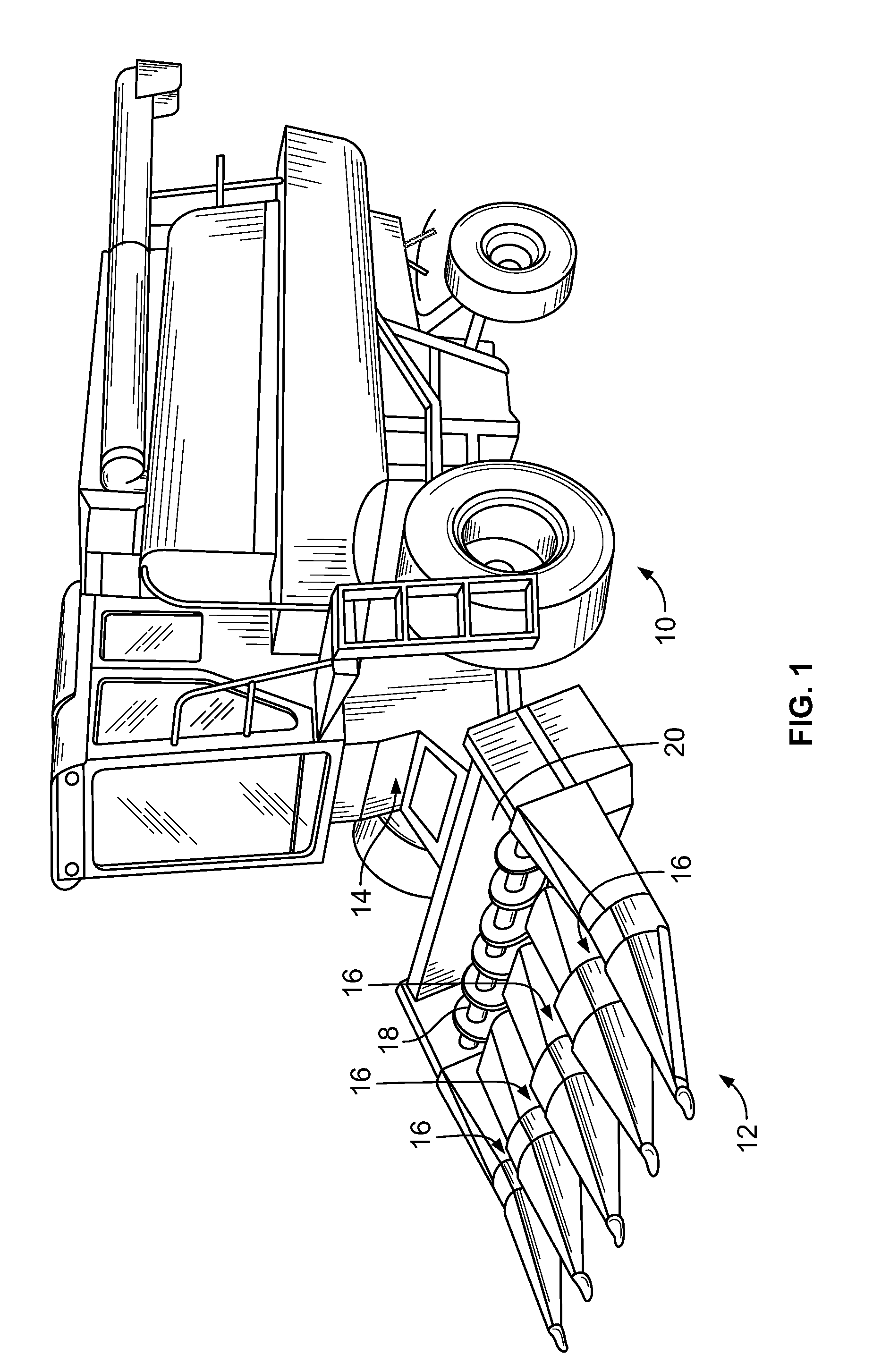
[0018]Referring now to the drawings, and particularly to FIG. 1, an agricultural combine of generally conventional construction is seen at 10. A corn harvesting header assembly, header assembly or cornhead 12 is mounted on combine 10, cantilevered in front of combine 10 and connected to the combine by a feeder assembly 14.

[0019]Header assembly 12 illustrated contains four row units 16, which harvest four rows of corn simultaneously. In other embodiments, the number of rows of corn that may be harvested may be different than four. Ears of corn are stripped from each of the four rows by a row unit 16 and then carried by an auger 18 in a trough 20 of a header assembly 12 to a feeder assembly 14. Feeder assembly 14 carries the collected ears rearwardly and upwardly into a threshing assembly (not shown) in the body of combine 10.

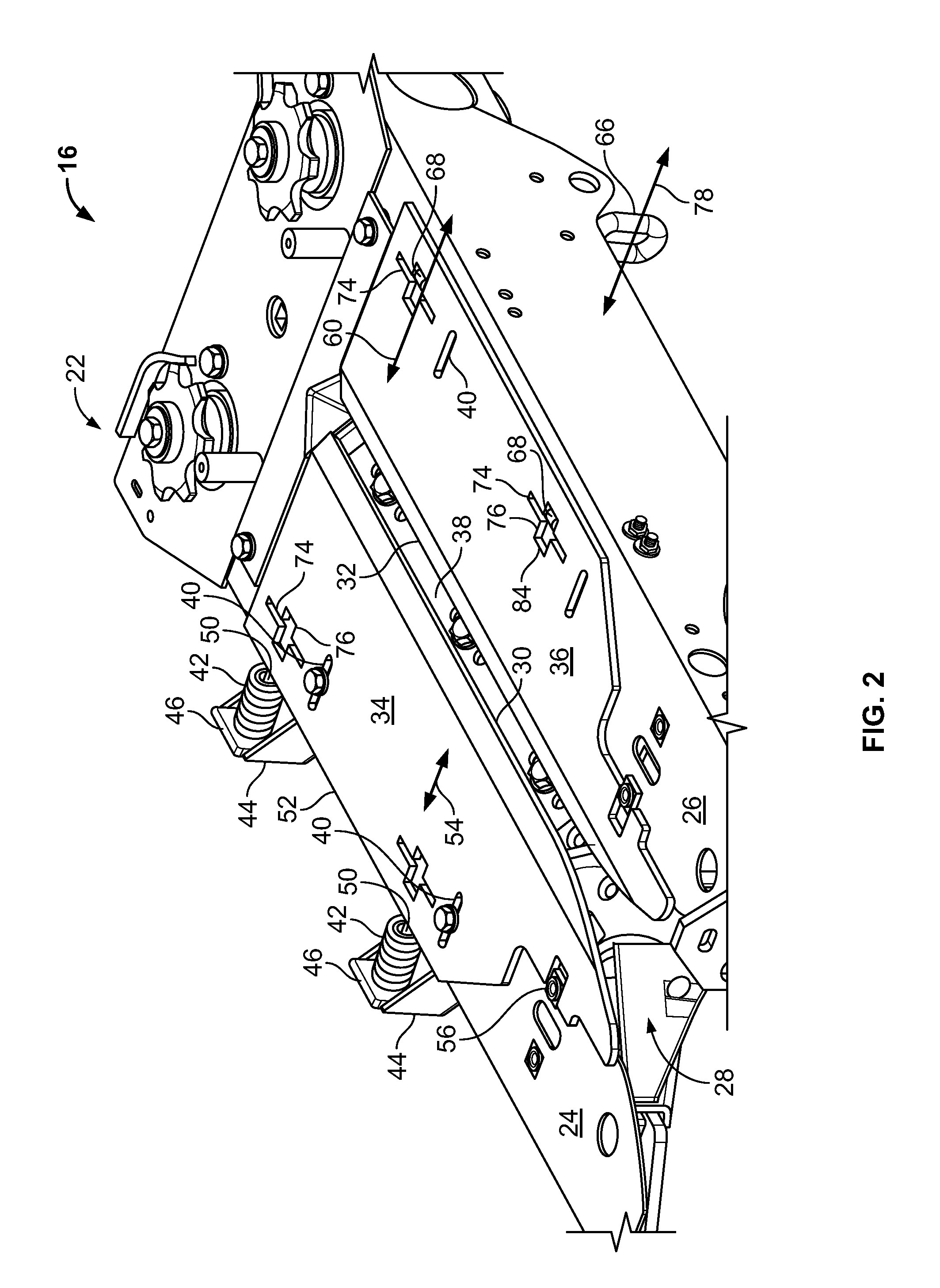
[0020]Referring now also to FIGS. 2 and 3, a row unit 16 is shown removed from header assembly 12. Row unit 16 gathers corn stalks as the row unit moves forwardl...


PUM


Abstract

A cornhead row unit is provided including first and second longitudinally extending stripper plates mounted on a frame and having opposed stripping edges which define a gap between them. The frame further includes a resilient device arranged and disposed to adjustably transversely urge the first stripper plate on the frame toward the second stripper plate to vary the width of the gap. An adjusting arrangement connecting the frame and the second stripper plate selectably and transversely moves the second stripper plate with respect to the first stripper plate to vary the width of the gap.

Description

FIELD OF THE INVENTION[0001]The invention relates in general to agricultural combines. It relates particularly to a corn harvesting header assembly for use with an agricultural combine.BACKGROUND OF THE INVENTION[0002]A corn harvesting header assembly or cornhead for an agricultural combine typically comprises a series of row units which are identical to each other. Each row unit includes a pair of snapping rolls having a snapping slot formed between them. Gathering chains having gathering fingers guide corn stalks into the snapping slot. The snapping rolls pull the corn stalks through the snapping slot and the ears are removed from the stalks as they come into engagement with opposed edges of stripper plates which bracket the slot between the gathering chains and the snapping rolls.[0003]It is conventional for at least one of the two stripper plates to be mounted on the row unit frame for movement toward and away from the other plate. This movement permits the gap between the oppos...

Claims


Application Information

Patent Timeline
Patent Type & Authority Applications(United States)
IPC IPC(8): A01D45/02
CPCA01D45/021
Inventor KOWALCHUK, TREVOR
Owner BLUE LEAF I P INC
Why Eureka
Try Eureka